Anode having an anode lead bonded to an active material layer, method of manufacturing of the anode, and battery including the anode

an anode lead and active material technology, applied in the direction of cell components, final product manufacturing, sustainable manufacturing/processing, etc., can solve the problems of lowering productivity, and method not practicable in manufacturing a battery electrode, so as to improve contact characteristics between the anode lead and the active material layer, lowering or fluctuating battery voltage, and preventing the increase of electrical resistance

Active Publication Date: 2014-05-20
MURATA MFG CO LTD
View PDF6 Cites 0 Cited by
  • Summary
  • Abstract
  • Description
  • Claims
  • Application Information

AI Technical Summary

Benefits of technology

[0016]According to the first anode of the embodiment of the invention, at least part of the bond region between the anode lead and the active material is made of copper or an alloy containing copper. According to the second anode of the embodiment of the invention, the anode lead is bonded to the active material layer with the bond made of copper or an alloy containing copper in between. Therefore, contact characteristics between the anode lead and the active material layer can be improved, and the electrical resistance can be prevented from increasing even though the anode lead is bonded to the active material layer. In the result, by structuring the first battery of the embodiment of the invention or the second battery of the embodiment of the invention by using the anode, lowering or fluctuation of the battery voltage, or lowering or fluctuation of the battery capacity can be reduced, and deterioration of the cycle characteristics can be prevented.
[0017]According to the first method of manufacturing an anode of the embodiment of the invention, the anode lead made of copper or an alloy containing copper in at least part of the bond region between the anode lead and the active material layer is bonded to the active material layer. According to the second method of manufacturing an anode of the embodiment of the invention, the anode lead is bonded to the active material layer with the bond made of copper or an alloy containing copper in between. Therefore, the first anode of the embodiment of the invention or the second anode of the embodiment of the invention can be easily manufactured.

Problems solved by technology

However, pattern deposition by a shutter mechanism has lead to a complex device structure and has caused lowering of productivity.
When using a mask or the like, many extraneous matters are attached on the mask in depositing plenty of materials, and thus such a method is not practical in manufacturing a battery electrode.
Therefore, there have been disadvantages such as lowering or fluctuation of the battery voltage, lowering or fluctuation of the battery capacity, and deterioration of the cycle characteristics.

Method used


Image

  • Anode having an anode lead bonded to an active material layer, method of manufacturing of the anode, and battery including the anode
  • Anode having an anode lead bonded to an active material layer, method of manufacturing of the anode, and battery including the anode
  • Anode having an anode lead bonded to an active material layer, method of manufacturing of the anode, and battery including the anode

Examples


first embodiment

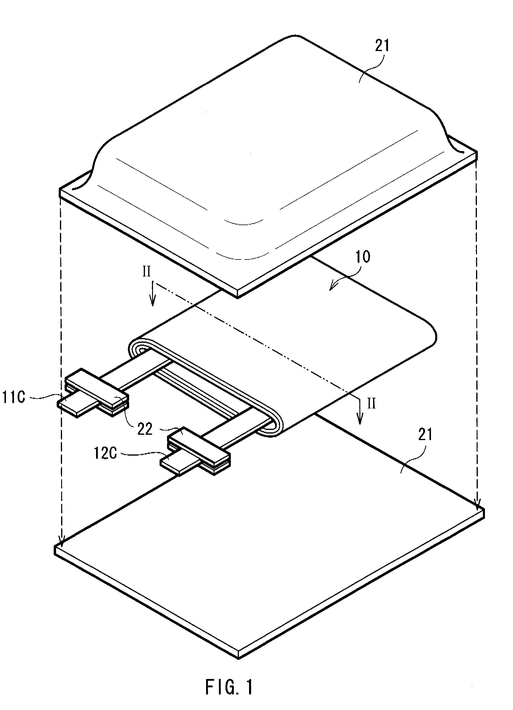
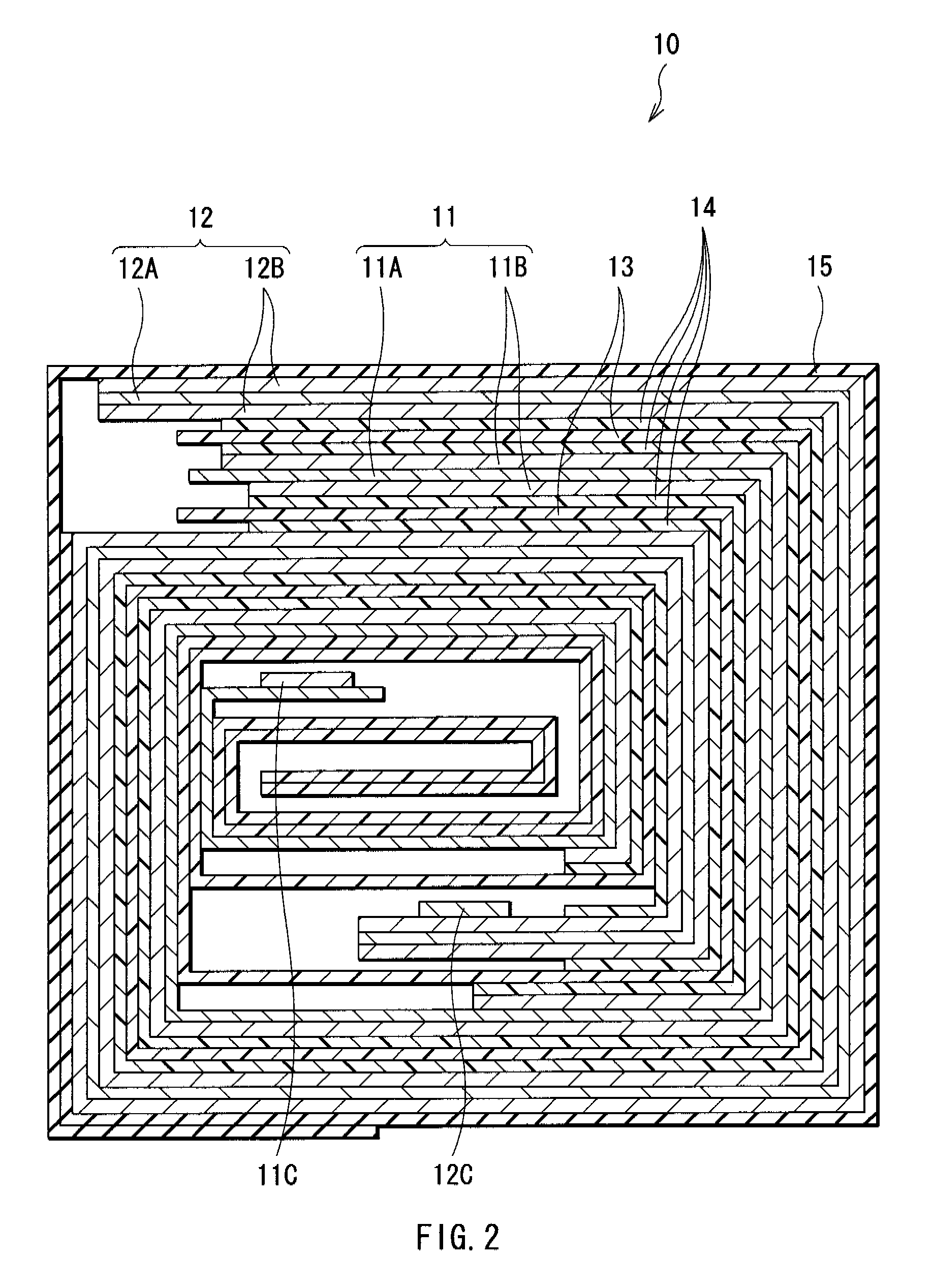
[0025]FIG. 1 shows a structure of a secondary battery according to a first embodiment of the invention. FIG. 2 shows a cross sectional structure taken along line II-II of a spirally wound electrode body shown in FIG. 1. The secondary battery is, for example, a lithium ion secondary battery, and has a structure that a flat spirally wound electrode body 10 is contained in a film package member 21.

[0026]The spirally wound electrode body 10 is obtained by layering and spirally winding a cathode 11 and an anode 12 with a separator 13 and an electrolyte layer 14 in between. The outermost periphery is protected by a protective tape 15.

[0027]The cathode 11 has a structure that an active material layer 11B is provided on a current collector 11A. The current collector 11A is made of, for example, aluminum, nickel, or stainless.

[0028]The active material layer 11B contains, for example, as a cathode active material, one or more cathode materials capable of inserting and extracting lithium (Li)....

second embodiment

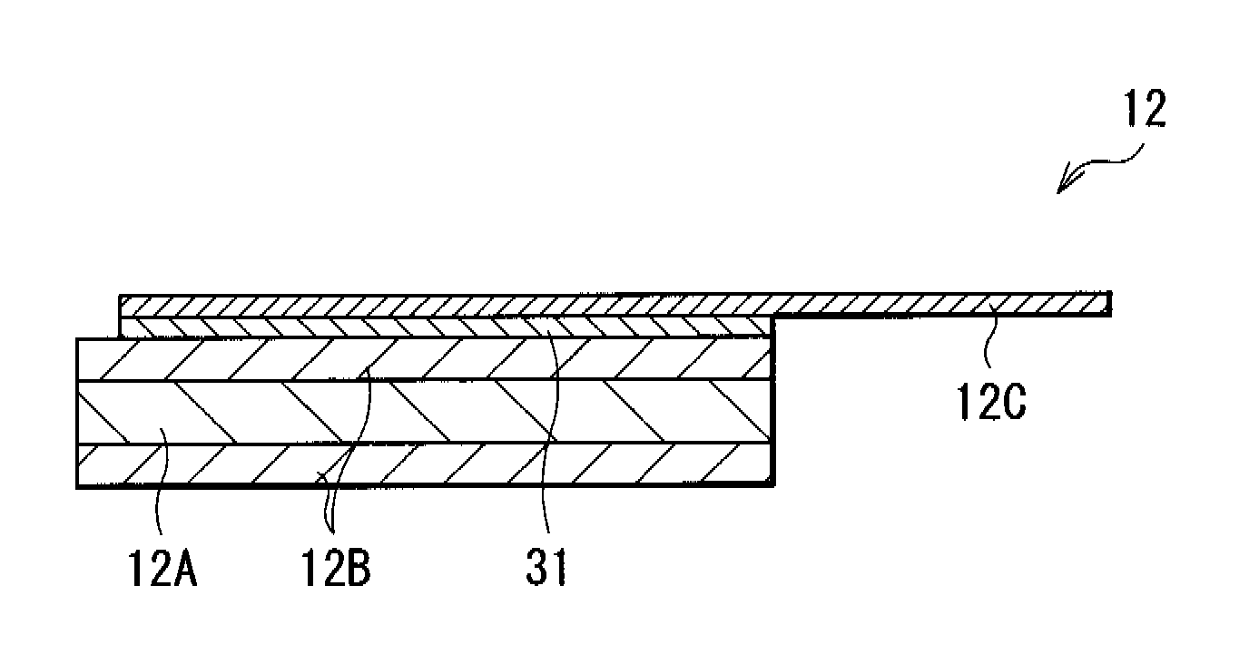
[0059]FIG. 5 shows a structure of an anode lead of a secondary battery according to a second embodiment of the invention in the longitudinal direction thereof. The secondary battery has the same structure as that of the secondary battery described in the foregoing first embodiment, except that the anode lead 12C is bonded to the active material layer 12B with a bond 31 made of copper or an alloy containing copper. Therefore, for the corresponding components, descriptions will be given with the identical referential characters affixed thereto.

[0060]The bond 31 is preferably alloyed with the active material layer 12B in at least part thereof. Thereby, the contact characteristics can be more improved. Further, the bond 31 may be alloyed with the anode lead 12C in at least part thereof.

[0061]The anode lead 12C is made of, for example, nickel, an alloy containing nickel, iron, or an alloy containing iron.

[0062]The secondary battery can be manufactured in the same manner as that of the se...

example 1

[0064]First, the current collector 12A made of a copper foil with surface roughness of about Rz=2 μm being 18 μm thick was prepared. On the current collector 12A, the active material layer 12B made of silicon being 5 μm to 6 μm thick was formed by vacuum vapor deposition method using electron beam heating method (electron beam vapor deposition method). The electron beam deposition was made on condition that a crystal silicon ingot was used as a raw material, electron beam was used as an evaporation source, and atmosphere of 1×10⁻² Pa or less was used. The deposition rate was 50 nm / sec.

[0065]Next, the anode lead 12C made of copper being 75 μm thick as shown in FIG. 3 was prepared. The anode lead 12C was bonded to the active material layer 12B in a manner that 5 points (10 spots) were bonded by two-spot resistance welding.

[0066]Further, 92 parts by weight of lithium cobaltate (LiCoO2) powder being 5 μm in an average particle diameter as a cathode active material, 3 parts by weight of ...


PUM

PropertyMeasurementUnit
surface roughnessaaaaaaaaaa
thickaaaaaaaaaa
deposition rateaaaaaaaaaa

Abstract

An anode which can improve contact characteristics between an active material layer and anode lead and can prevent electrical resistance from increasing, a method of manufacturing the anode, and a battery including the anode are provided. An active material layer containing silicon as an element is provided on a current collector. An anode lead is bonded to the active material layer. At least part of a bond region between the anode lead and the active material layer is made of copper or an alloy containing copper. Thereby, the electrical resistance can be prevented from being increased even though the anode lead is bonded to the active material layer. The anode lead may be made of copper or an alloy containing copper. Otherwise, coating layer made of copper or an alloy containing copper may be provided on the surface of a base.

Description

CROSS REFERENCES TO RELATED APPLICATIONS[0001]The present invention contains subject matter related to Japanese Patent Application JP 2005-302631 filed in the Japanese Patent Office on Oct. 18, 2005, the entire contents of which being incorporated herein by reference.BACKGROUND OF THE INVENTION[0002]1. Field of the Invention[0003]The present invention relates to an anode provided with an active material layer containing silicon (Si) as an element, a method of manufacturing the anode, and a battery including the anode. In particular, the invention relates to an anode suitable for forming an active material layer by vapor-phase deposition method, a method of manufacturing it, and a battery including it.[0004]2. Description of the Related Art[0005]In recent years, as mobile devices have been sophisticated and multi-functionalized, a higher capacity of secondary batteries as a power source for these mobile devices has been demanded. As a secondary battery to meet such a demand, there is...

Claims


Application Information

Patent Timeline
Patent Type & Authority Patents(United States)
IPC IPC(8): H01M4/38H01M4/02H01M10/05H01M4/58H01M4/1395H01M4/134H01M2/26
CPCY02E60/122H01M4/134H01M2/22H01M4/661H01M10/052H01M2/32H01M50/528H01M50/571Y02E60/10Y02P70/50H01M4/13H01M4/139H01M4/66H01M10/05
Inventor KONISHIIKE, ISAMUKAWASE, KENICHI
Owner MURATA MFG CO LTD
Why Eureka
Try Eureka