
Bifacial solar cell

a solar cell and bifacial technology, applied in the field of bifacial solar cells, can solve the problems of low current conversion efficiency of solar cells, and achieve the effect of improving the contact characteristic between the p-type electrode part and the p+-type doped region

Active Publication Date: 2013-07-25
SHANGRAO JINKO SOLAR TECH DEV CO LTD
View PDF2 Cites 4 Cited by
  • Summary
  • Abstract
  • Description
  • Claims
  • Application Information

AI Technical Summary

Benefits of technology

The patent text describes a method to improve the contact between a specific part of a semiconductor device and the p+-type doped region, as well as the adhesion between this part and an interconnector. This is achieved through the use of two different powders, which are applied to the specific part of the semiconductor device during manufacturing. The technical effect of this method is to improve the overall performance of the semiconductor device.

Problems solved by technology

Because light is generally incident only on one surface of the substrate of the solar cell, a current conversion efficiency of the solar cell is low.

Method used


Image

  • Bifacial solar cell
  • Bifacial solar cell
  • Bifacial solar cell

Examples


Embodiment Construction

[0026]Reference will now be made in detail to embodiments of the invention, examples of which are illustrated in the accompanying drawings. This invention may, however, be embodied in many different forms and should not be construed as limited to the embodiments set forth herein. Wherever possible, the same reference numbers will be used throughout the drawings to refer to the same or like parts. It will be noted that a detailed description of known arts will be omitted if it is determined that the known arts can obscure the embodiments of the invention.

[0027]In the drawings, the thickness of layers, films, panels, regions, etc., are exaggerated for clarity. It will be understood that when an element such as a layer, film, region, or substrate is referred to as being “on” another element, it can be directly on the another element or intervening elements may also be present. In contrast, when an element is referred to as being “directly on” another element, there are no intervening e...


PUM


Abstract

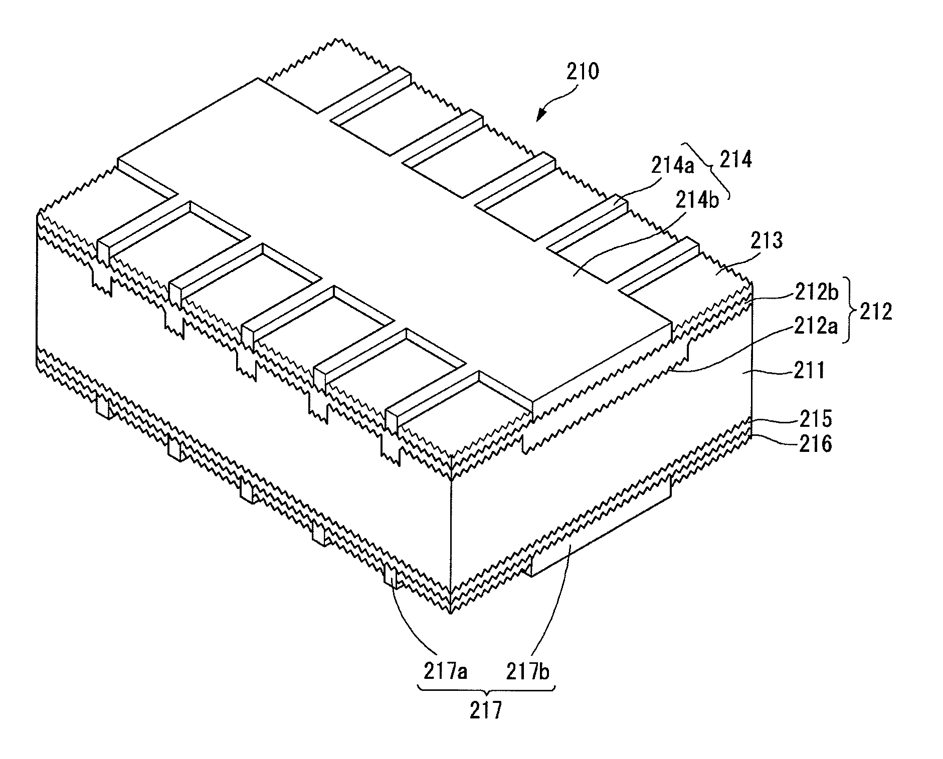
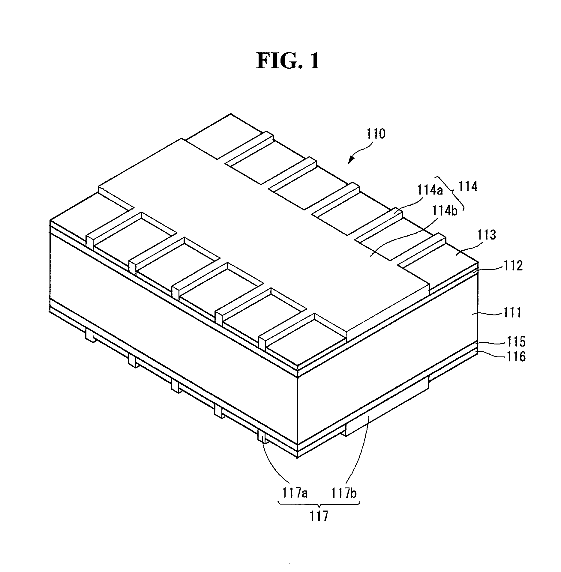
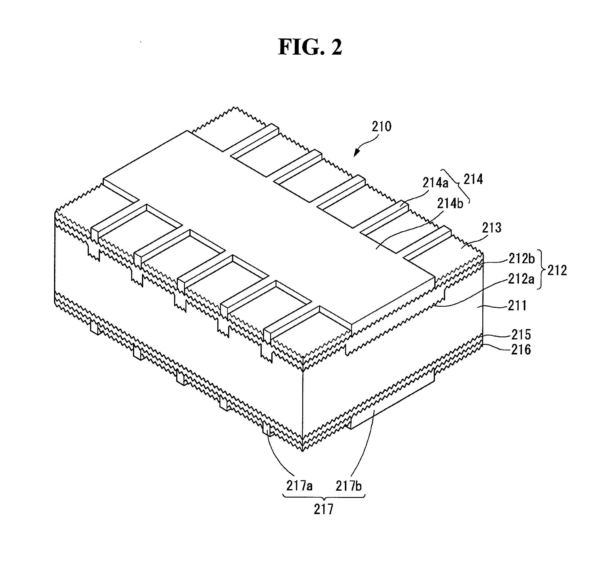
A bifacial solar cell is discussed. The bifacial solar cell includes a substrate, a p+-type doped region positioned at a first surface of the substrate, a P-type electrode part electrically connected to the p+-type doped region, an n+-type doped region positioned at a second surface of the substrate, and an N-type electrode part electrically connected to the n+-type doped region. The P-type electrode part is formed of a first inorganic solid powder including a first powder, which contains silver (Ag) and has an average diameter of about 0.2 μm to 1 μm, and a second powder, which contains a group III element and has an average diameter of about 1 μm to 5 μm. The N-type electrode part is formed of a second inorganic solid powder including only the first powder.

Description

[0001]This application claims priority to and the benefit of Korean Patent Application No. 10-2012-0006525 filed in the Korean Intellectual Property Office on Jan. 20, 2012, the entire contents of which are incorporated herein by reference.BACKGROUND OF THE INVENTION[0002]1. Field of the Invention[0003]Embodiments of the invention relate to a bifacial solar cell.[0004]2. Description of the Related Art[0005]Solar power generation to convert light energy into electric energy using a photoelectric conversion effect has been widely used as a method for obtaining eco-friendly energy. A solar power generation system using a plurality of solar cell modules has been installed in places, such as houses, due to an improvement of a photoelectric conversion efficiency of solar cells.[0006]A solar cell generally includes a substrate and an emitter region forming a p-n junction along with the substrate. The solar cell generates an electric current using light incident through one surface of the s...

Claims


Application Information

Patent Timeline
Patent Type & Authority Applications(United States)
IPC IPC(8): H01L31/0224H01L31/0236H01L31/0232
CPCH01L31/022425Y02E10/547H01L31/1804H01L31/0684Y02P70/50H01L31/042H01L31/0224
Inventor KIM, SUNGJINCHO, HAEJONGBYUN, YANGWOOLEE, SEONGEUN
Owner SHANGRAO JINKO SOLAR TECH DEV CO LTD
Learn More