Method for identification of a light inductive charger

a technology of inductive charger and light source, which is applied in the direction of safety/protection circuit, electrochemical generator, instruments, etc., can solve the problems of increased acquisition cost of these devices, complicated circuit layout, and inconvenient keeping and carrying of these devices, so as to reduce the use of electronic components, simplify the overall circuit layout, and low cost design

Active Publication Date: 2014-05-20
FU TONG TECH
View PDF9 Cites 15 Cited by
  • Summary
  • Abstract
  • Description
  • Claims
  • Application Information

AI Technical Summary

Benefits of technology

[0009]A primary object of the present invention is to install a light receiver and a light emitter on the emitting terminal of the power base and the receiving terminal of the wireless charging receiver as a simple identifying device, so that the microprocessor of the emitting terminal can determine the corresponding receiving terminal according to the light receiving state of the light receiver, and the power base can emit energy of wireless electromagnetic waves to the receiving terminal for charging purpose. Besides, as the receiving terminal only requires simple circuit configuration for receiving power energy and it is not necessary to install a microprocessor on the wireless charging receiver, this can simplify overall circuit layout, significantly reduce use of electronic components, and make low-cost design be widely adopted in electronic products of low unit prices (e.g. toys, home phones or remote controllers), thus achieving wireless charging effect.
[0010]A secondary object of the present invention is to enable the microprocessor of the emitting terminal of the power base to automatically analyze characteristics of coil oscillation of the power supply resonance circuit by using a voltage measurement circuit, optimize power output through frequency conversion control of output energy, reduce loss of energy in the process of transmission, and convert additional power, so as to achieve the effect of frequency conversion chargers and power saving. At the same time, a display module is fixed to display the corresponding system time, charging time, charging status and other parameters in a multi-function mode, thus making it convenient for users to be fully aware of the current status.
[0011]A further object of the present invention is to enable the emitting terminal of the power base to enter into sleep mode when no wireless charging receiver is placed on the power base, so as to reduce power consumption, save electricity, reduce operation costs and improve operation safety.

Problems solved by technology

However, as portable electronic devices of different firms have different specifications and have specific chargers compatible with the devices, when a new portable electronic device is bought, an additional charger is required to be compatible with it, thus making the acquisition cost for these devices increase significantly.
Besides, if there are many chargers for portable electronic devices, it will cause considerable convenience in management and require some room for these chargers, thus making it not convenient to keep and carry them for use.
If the receiving terminal is not a designed charger at this moment, the power energy will heat up the metal objects and may cause dangers.
However, such charging devices need to transmit signals through wireless communication, thus requiring microprocessors or detection chips to be installed at the receiving terminal.
This will result in complicated circuit layout and high production costs of these charging devices.
Moreover, high-cost design is not applicable to electronic products with low unit prices, and this will limit the scope of its use and needs to be solved by those engaged in this field through optimized design.

Method used


Image

  • Method for identification of a light inductive charger
  • Method for identification of a light inductive charger
  • Method for identification of a light inductive charger

Examples


Embodiment Construction

[0016]To achieve the aforesaid objects and functions as well as the techniques adopted in the present invention and its fabrication, examples of the preferred embodiment of the present invention are given below to illustrate features and functions of the present invention in detail by referring to the accompanying drawings.

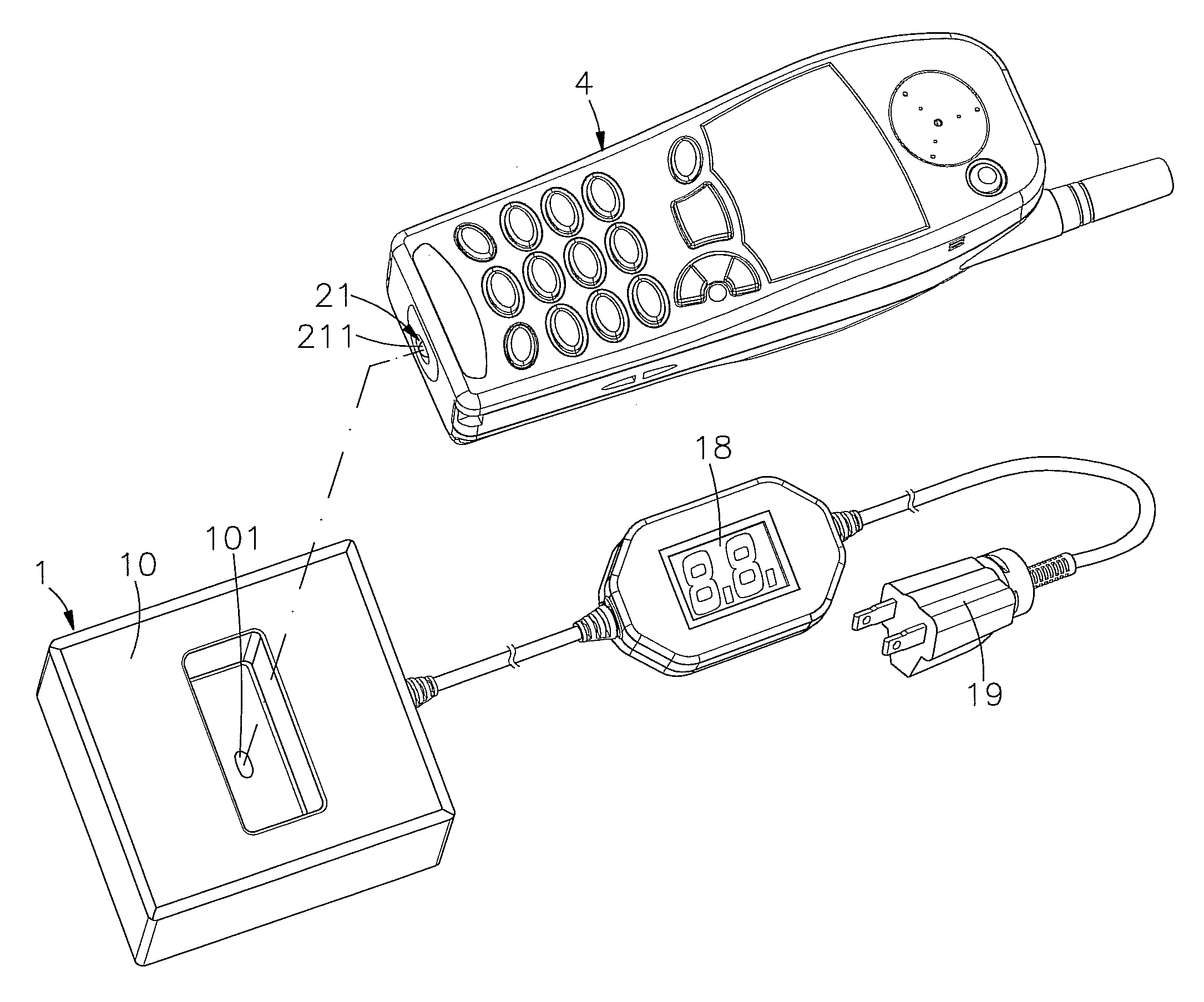
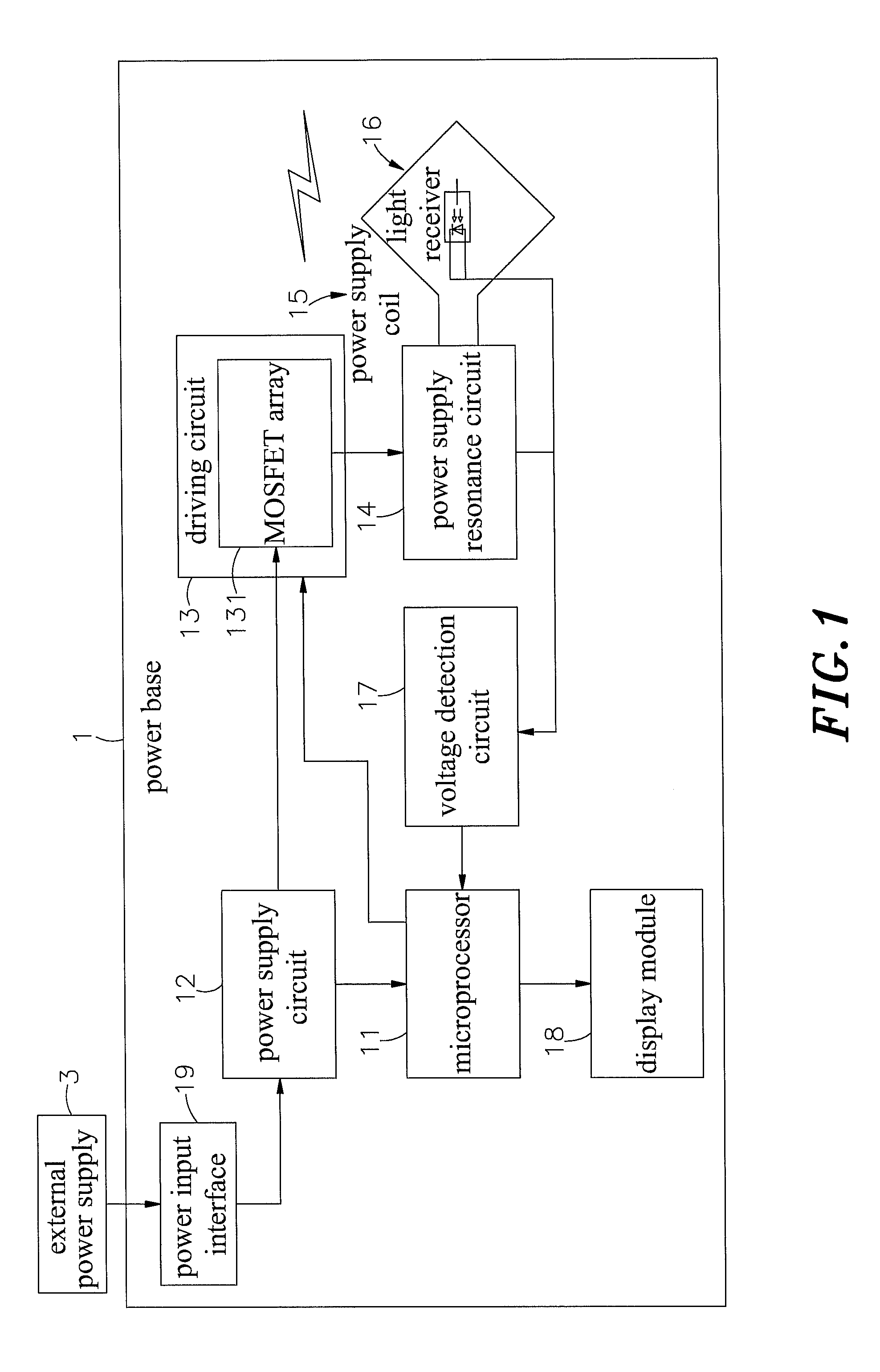
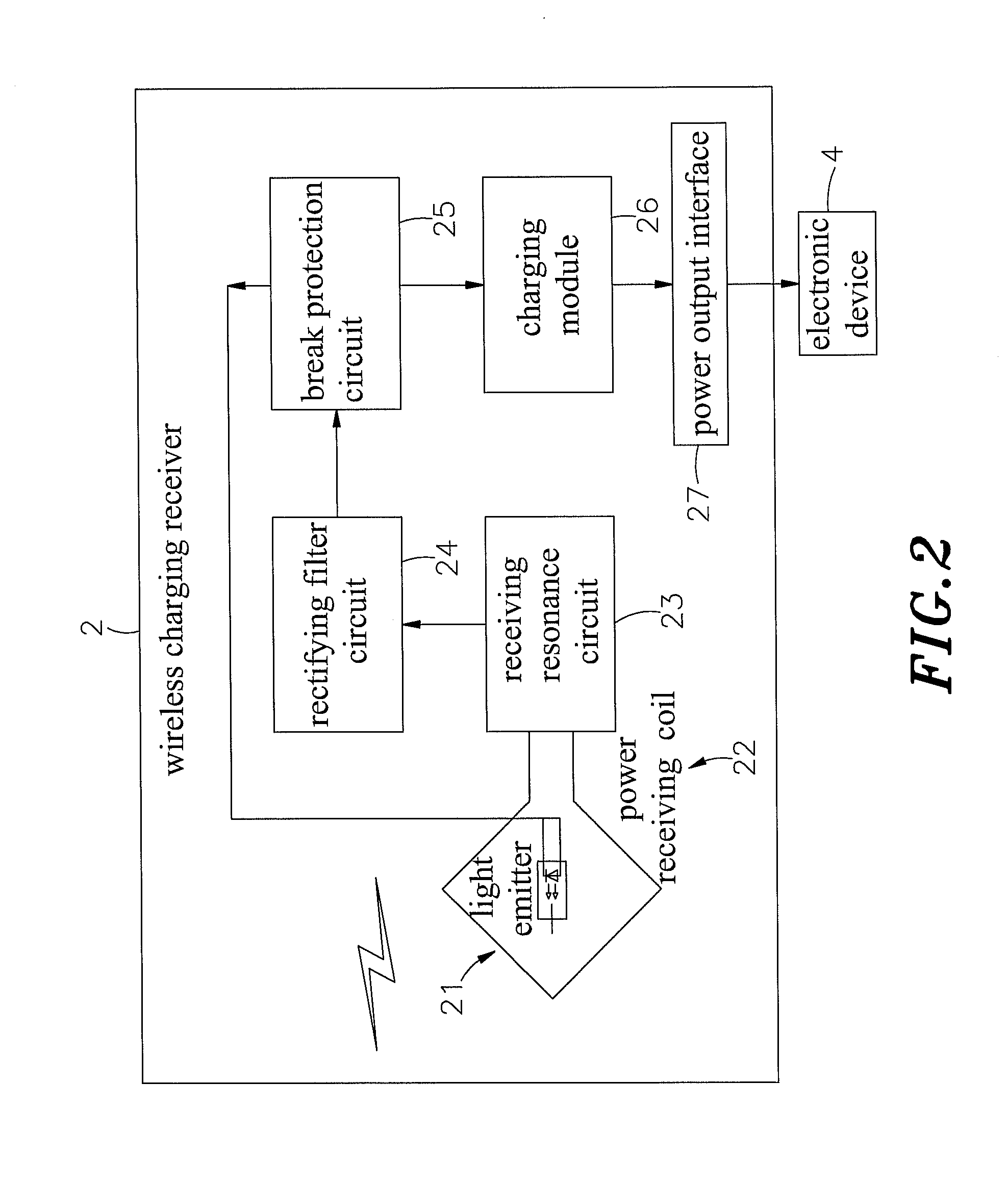
[0017]Refer to FIGS. 1, 2 and 3, which are respectively a block diagram of a power base, a block diagram of a wireless charging receiver and a flow chart of steps according to the present invention. As shown clearly in these figures, the present invention includes a power base 1 and a wireless charging receiver 2, wherein:

[0018]The power base 1 contains a body 10 in which a circuit board with proposed circuit layout and electronic components is fixed, and the circuit board includes a microprocessor 11 electrically connected to a power supply circuit 12 that connects to an external power supply 3 and supplies low-voltage electricity to the microprocessor 11. Beside...


PUM

PropertyMeasurementUnit
timeaaaaaaaaaa
timeaaaaaaaaaa
brightnessaaaaaaaaaa

Abstract

The present invention relates to a method for identification of a light inductive charger, in which a power base includes a light receiving hole to expose a light receiver, and a light emitting component is established in a light emitter of a wireless charging receiver to emit lights towards the light receiving hole. The power base transmits electromagnetic wave energy to the receiving terminal for a short period of time when finding it covered by an object, in a dark place or covered by the wireless charging receiver after having received lights from the light receiver and transmitted the signals to the microprocessor via a voltage detection circuit. The charging module of the wireless charging receiver, if not fully charged, feeds back light signals for the same time period to indicate that charging is required. Then charging energy of electromagnetic waves will be emitted to start charging.

Description

[0001]This application claims the priority benefit of The People's Republic of China patent application number 201010190732.3, filed on Jun. 3, 2010.BACKGROUND OF THE INVENTION[0002]1. Field of the Invention[0003]The present inventions relates to a method for identification of a light inductive charger, particularly to the method in which a light receiver and a light emitter are installed on the emitting and receiving terminals of the wireless charging receiver as an identifying device, and the microprocessor of the emitting terminal determines the corresponding receiving terminal according to the light receiving state of the light receiver, so that wireless power energy is emitted to the receiving terminal for charging purpose.[0004]2. Description of the Related Art[0005]Nowadays, the age of electronics technology and worldwide access of Internet make various kinds of digital products, for example, digital cameras, mobile phones, multimedia video and audio players (MP3, MP4 or MP5 ...

Claims


Application Information

Patent Timeline
Patent Type & Authority Patents(United States)
IPC IPC(8): H01F38/14H02J7/00
CPCH01M10/46H02J7/025H02J7/027Y02E60/12Y02E60/10H02J7/02H02J7/0029H02J7/0047H02J7/0049H02J50/12H02J50/90H02J50/80
Inventor TSAI, MING-CHIUCHAN, CHI-CHE
Owner FU TONG TECH
Why Eureka
Try Eureka