Slot-type induction charger

a charger and induction technology, applied in the field of induction chargers, can solve the problems of inconvenient carrying and storage of many different mobile electronic devices and the related mating battery chargers, and the inability to economically purchase respective mating battery chargers, and achieve the effect of less installation spa

Active Publication Date: 2014-05-20
FU TONG TECH
View PDF9 Cites 39 Cited by
  • Summary
  • Abstract
  • Description
  • Claims
  • Application Information

AI Technical Summary

Benefits of technology

[0011]To achieve this and other objects of the present invention, a slot-type induction charger comprises a power base and an induction charging receiver. The power base comprises a base member defining therein a slot, a control module mounted in the slot of the base member and a power-supplying coil module mounted in the slot and electrically coupled to the control module for creating oscillation to emit an electric energy. The induction charging receiver is set in the slot of the base member of the power base for receiving the electric energy from the power-supplying coil module by electromagnetic induction for charging an electromagnetic device. The induction charging receiver comprises an expansion base, a charging module mounted in the expansion base and a power-receiving coil module mounted in the expansion base and electrically coupled to the charging module and adapted for receiving the electric energy from the power-supplying coil module by means of electromagnetic induction. The expansion base comprises an electric connector for the connection of an electromechanical device to be charged. The power-supplying coil module and the power-receiving coil module each comprise a magnetic conductor, a plurality of first coils and at least one second coil alternatively wound round the magnetic conductor in reversed directions and electrically connected in series, and an induction zone defined between each second coil and each adjacent first coil. Thus, the use of the induction charging receiver does not increase the thickness of the attached electromechanical device, and the slot-type induction charger does not require much installation space and can be installed in a narrow space area in a car, i.e., the slot-type induction charger has light, thin, short and small characteristics.
[0012]In an alternate form of the present invention, the slot-type induction charger comprises one power base and two induction charging receivers set in the slot of the base member of the power base. Thus, the slot-type induction charger can charge two electronic devices at a time. Further, the base member of the power base can be installed in an interior decorative panel (dashboard, handrail fitting or door panel) or the center console of a car. Alternatively, the slot-type induction charger of the present invention can be embedded in a computer peripheral device (keyboard, mouse, wireless tablet), stereo head unit, game machine head unit, electric home appliance, or any of a variety of other peripheral devices. Further, with the position limitation effect of the slot of the base member of the power base, the induction charging receiver(s) with the attached electromechanical device(s) are kept in high stability and will not fall out of the power base accidentally when the car carrying the slot-type induction charger is vibrating, protecting the electromechanical device(s) from scratches and other damage.

Problems solved by technology

However, when using an electronic device for mobile application, the first problem to be solved is the supplying of power supply.
However, it is not economic to purchase a respective mating battery charger when buying a new mobile electronic device.
Further, it is inconvenient to carry and store many different mobile electronic devices and the related mating battery chargers.
Thus, a wireless battery charger can charge different electronic devices, eliminating the drawbacks of conventional power supply devices that cannot give mutual support, are not interchangeable and inconvenient for carrying.
During transmission of the induced electric current, the transmitted electric energy may be partially received by surrounding components, causing heat damage.
However, it is expensive and not easy to make a magnetic material having a reflective or absorptive characteristic relative to electromagnetic waves.
However, because the planar spiral coil A1 is close to a circular shape, not convenient for installation in a compact handheld electronic device.
In consequence, the application of conventional induction type power supply devices or wireless battery chargers is limited.

Method used


Image

  • Slot-type induction charger
  • Slot-type induction charger
  • Slot-type induction charger

Examples


Embodiment Construction

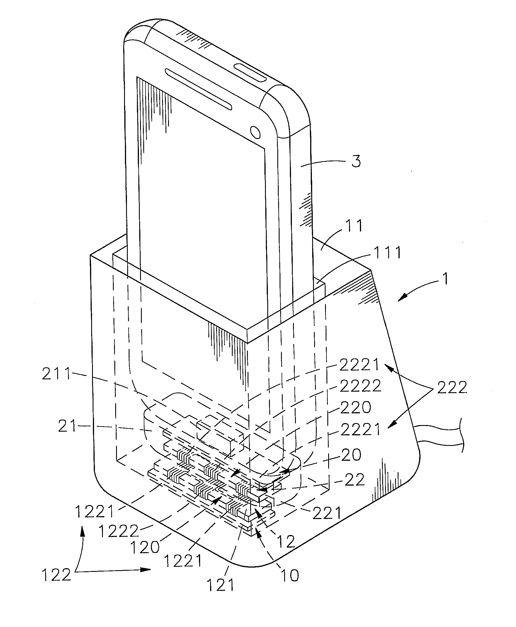
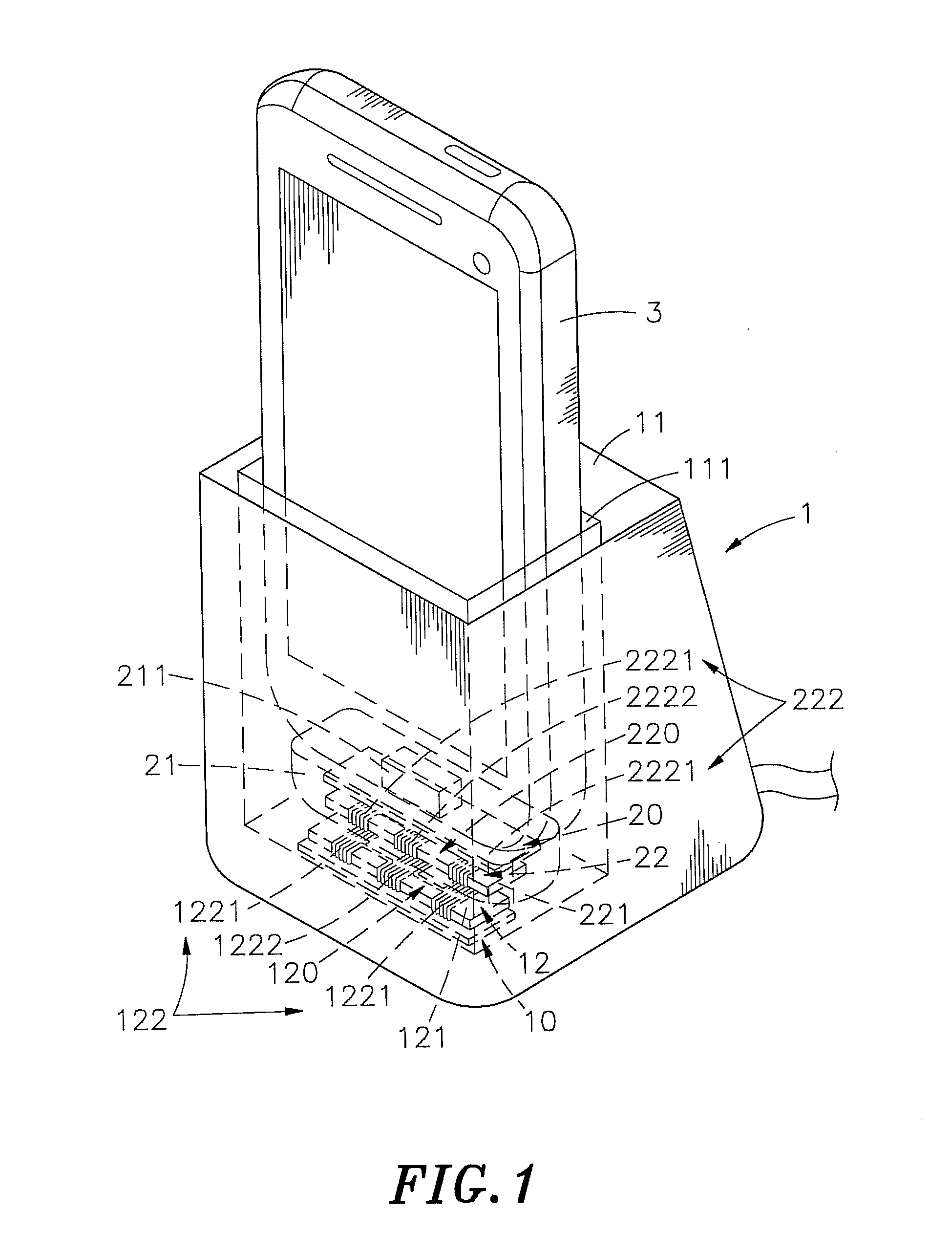
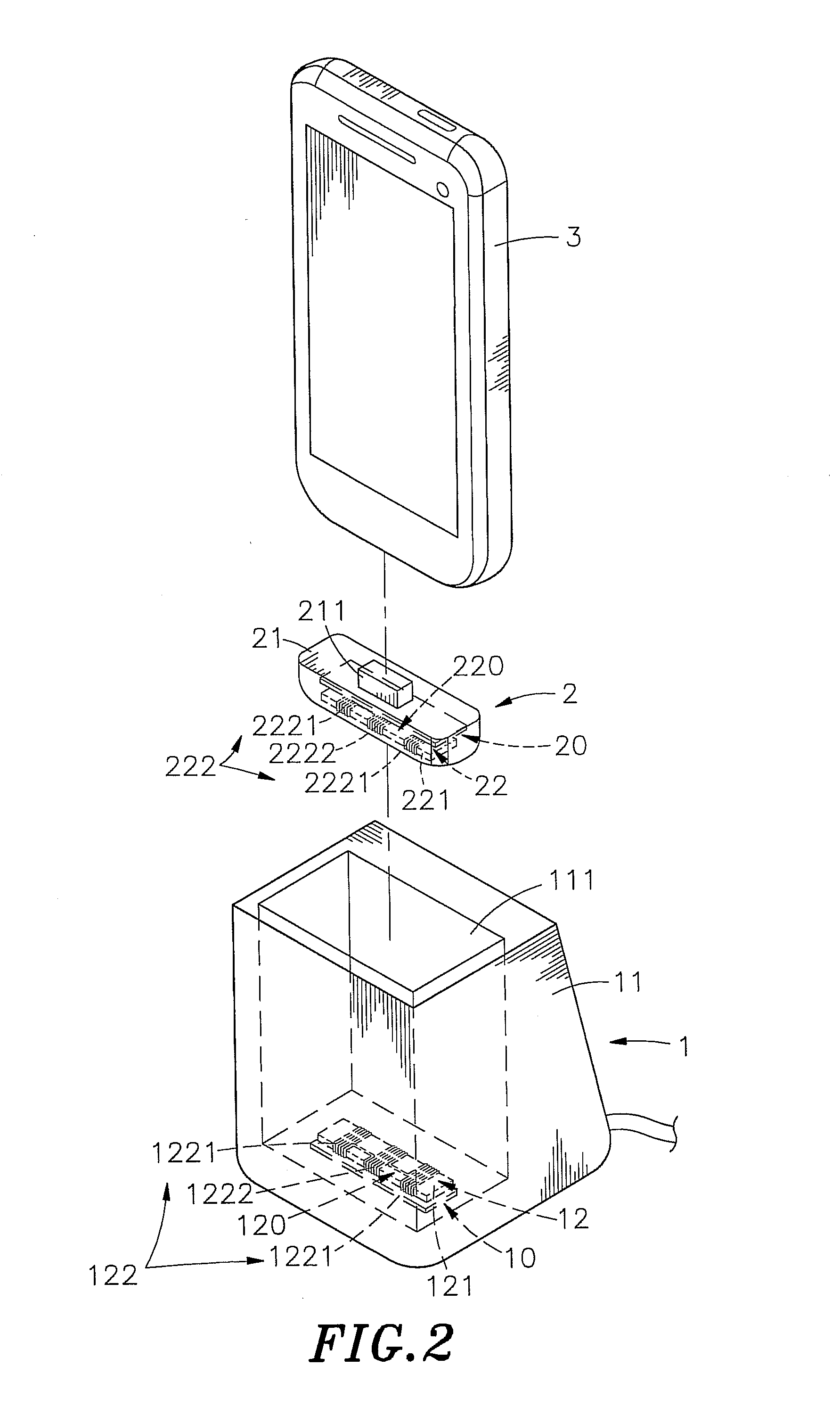
[0023]Referring to FIGS. 1˜4, a slot-type induction charger in accordance with the present invention is shown comprising a power base 1 and an induction charging receiver 2.

[0024]The power base 1 comprises a base member 11, a control module 10 mounted in the base member 11, and a power-supplying coil module 12 mounted in the base member 11 and electrically coupled to the control module 10. The base member 11 defines therein a slot 111 for accommodating the induction charging receiver 2 and an electromechanical device 3. The power-supplying coil module 12 comprises a power-supplying magnetic conductor 121 and power-supplying induction coils 122. The power-supplying magnetic conductor 121 is an elongated flat bar. The power-supplying induction coils 122 are formed of one single insulated conducting wire 1220 that is wound round one end of the power-supplying magnetic conductor 121 through a predetermined number of turns in a first direction (clockwise direction) to form a first power-...


PUM


Abstract

A slot-type induction charger having light, thin, short and small characteristics is disclosed to include a power base holding therein a control module and a power-supplying coil module in a base member thereof for inducing an electric current, and an induction charging receiver set in the base member for receiving the induced electric current by electromagnetic induction from the power base for charging an electromagnetic device being connected to an electrical connector thereof. The power-supplying coil module and the power-receiving coil module each includes a magnetic conductor and a series of coils being alternatively and reversely wound around the magnetic conductor.

Description

[0001]This application is a Continuation-In-Part of application Ser. No. 13 / 276,014, filed on Oct. 18, 2011, now pending. The patent application identified above is incorporated here by reference in its entirety to provide continuity of disclosure.BACKGROUND OF THE INVENTION[0002]1. Field of the Invention[0003]The present invention relates to battery charging technology and more particularly, to a slot-type induction charger, which uses an induction charging receiver in a narrow slot of a thin thickness power base to receive an induced electric current from a power-supplying coil module of the power base by means of electromagnetic induction for charging an electromagnetic device being attached thereto.[0004]2. Description of the Related Art[0005]Following fast development of electronic and multimedia information technologies, notebook computer, tablet computer, smart mobile phone, PDA and many other handheld electronic devices have been continuously developed and have appeared on t...

Claims


Application Information

Patent Timeline
Patent Type & Authority Patents(United States)
IPC IPC(8): H02J7/00
CPCH02J7/0044H02J7/025H02J5/005H02J50/005H02J50/12
Inventor TSAI, MING-CHIUCHAN, CHI-CHE
Owner FU TONG TECH
Why Eureka
Try Eureka