Power envelope controller and method

a controller and power envelope technology, applied in the direction of amplifiers with field-effect devices, single-ended push-pull amplifiers, gain control, etc., can solve the problems of over-designed cooling for the majority of users, slow response, and not necessarily robust, so as to reduce the power dissipation

Active Publication Date: 2014-05-20
KEITHLEY INSTRUMENTS INC
View PDF4 Cites 2 Cited by
  • Summary
  • Abstract
  • Description
  • Claims
  • Application Information

AI Technical Summary

Problems solved by technology

This usually results in over-designed cooling for the majority of users since sinkmode is typically used less often than sourcemode.
Sometimes thermal monitoring is performed in the background, which is slow to respond and not necessarily robust.

Method used


Image

  • Power envelope controller and method
  • Power envelope controller and method
  • Power envelope controller and method

Examples


Embodiment Construction

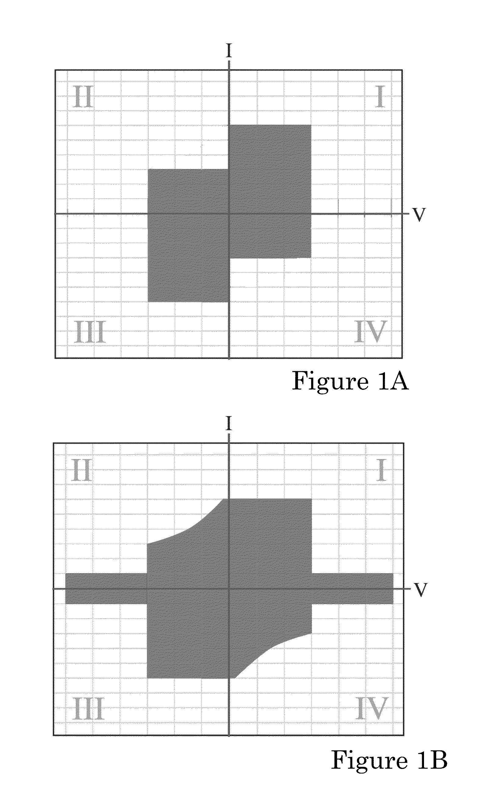
[0013]Disclosed herein is an apparatus and method that provides improved techniques for monitoring the safe operating areas of an SMU in both source and sinkmode operation. Assume an SMU is designed with a sourcemode upper limit of 200 W. Using the 2× sinkmode design criteria, this would require an upper limit of 400 W for sinkmode operation. Such a design would require large heatsinks and elaborate cooling designs. The alternative would be an asymmetric power envelope as shown in FIG. 1A. It should be understood that the SMU may be configured with multiple voltage or current ranges, e.g., ±3000V@20 mA and ±1500V@120 mA. FIG. 1A shows a power envelope where the sinkmode power is limited based on the selected range yielding a stepped shape in quadrants II and IV. This solution leaves the user with an awkward transition at the threshold from source to sink mode and eliminates capability that the user would otherwise benefit from (power within the designed 200 W internal capability).

[0...


PUM


Abstract

A power envelope controller configured for use with an amplification stage and method are disclosed. The power envelope controller includes voltage feedback input circuitry configured to receive a voltage feedback signal representing an internal voltage drop across the amplification stage and current feedback input circuitry configured to receive a current feedback signal representing an output current of the amplification stage. An analog multiplier is configured to generate an internal power dissipation signal representing the internal power dissipation of the amplification stage based on the voltage and current feedback signals. A comparator circuit is configured to compare the internal power dissipation signal to a power threshold and generate a power control error signal when the internal power dissipation of the amplification stage exceeds the threshold.

Description

FIELD OF INVENTION[0001]This invention relates generally to power amplifiers and, more particularly, to power amplifiers capable of source and sink mode operation.BACKGROUND[0002]Source measure units (SMU) are used to make precision measurements in many fields, including the testing of semiconductor products. For example, U.S. Pat. No. 5,039,934 describes one such device and range-changing in such a device is described in U.S. Pat. No. 5,144,154, both of which are incorporated herein by reference in their entireties. Source measure units force either a voltage or a current and then respectively measure a resulting current or voltage. SMUs may operate in source or sink mode. Internal power dissipation is equal to the output current multiplied by the difference in the internal voltage supply and the output voltage. Because sinkmode current is returned to the opposite voltage supply rail internally, the internal power dissipation in sinkmode is twice the maximum internal power dissipat...

Claims


Application Information

Patent Timeline
Patent Type & Authority Patents(United States)
IPC IPC(8): H03F1/52
CPCH03F3/21H03F3/16
Inventor RICE, MARTIN J.
Owner KEITHLEY INSTRUMENTS INC
Why Eureka
Try Eureka