Compact CO2 slab-laser

a co2 slab and laser technology, applied in the direction of instruments, optical elements, active medium materials, etc., can solve the problems of not reducing the basic cost and effort of building, cooling, and interconnecting separate enclosures

Active Publication Date: 2014-05-20
COHERENT INC
View PDF20 Cites 11 Cited by
  • Summary
  • Abstract
  • Description
  • Claims
  • Application Information

AI Technical Summary

Problems solved by technology

This of course does not reduce basic cost and effort of building, cooling, and interconnecting the separate enclosures.

Method used


Image

  • Compact CO2 slab-laser
  • Compact CO2 slab-laser
  • Compact CO2 slab-laser

Examples


Embodiment Construction

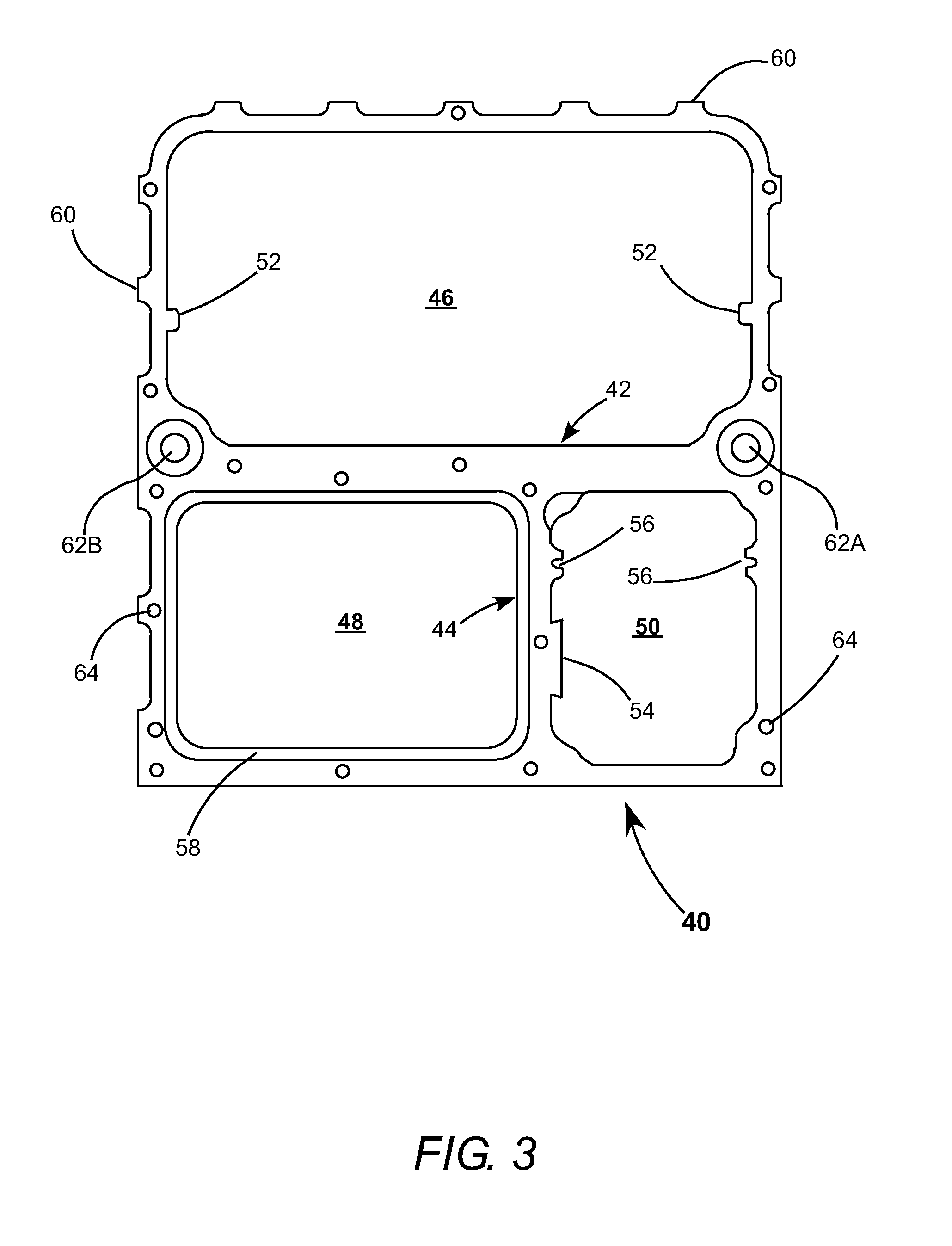
[0037]Referring now to the drawings, wherein like components are designated by like reference numerals, FIG. 3 is an un-shaded lateral cross-section view schematically illustrating schematically illustrating an laser enclosure 40 in accordance with the present invention. The enclosure is formed primarily from a custom made aluminum extrusion, and is divided by internal walls 42 and 44 into separate compartments 46, 48 and 50. The compartments are hermetically sealed by end flanges which are not shown in FIG. 3 but are depicted in higher-numbered drawings and discussed further herein below. Exemplary external dimensions of the extrusion are a length of about forty-four inches, a height of about eight inches, and a width of about seven inches.

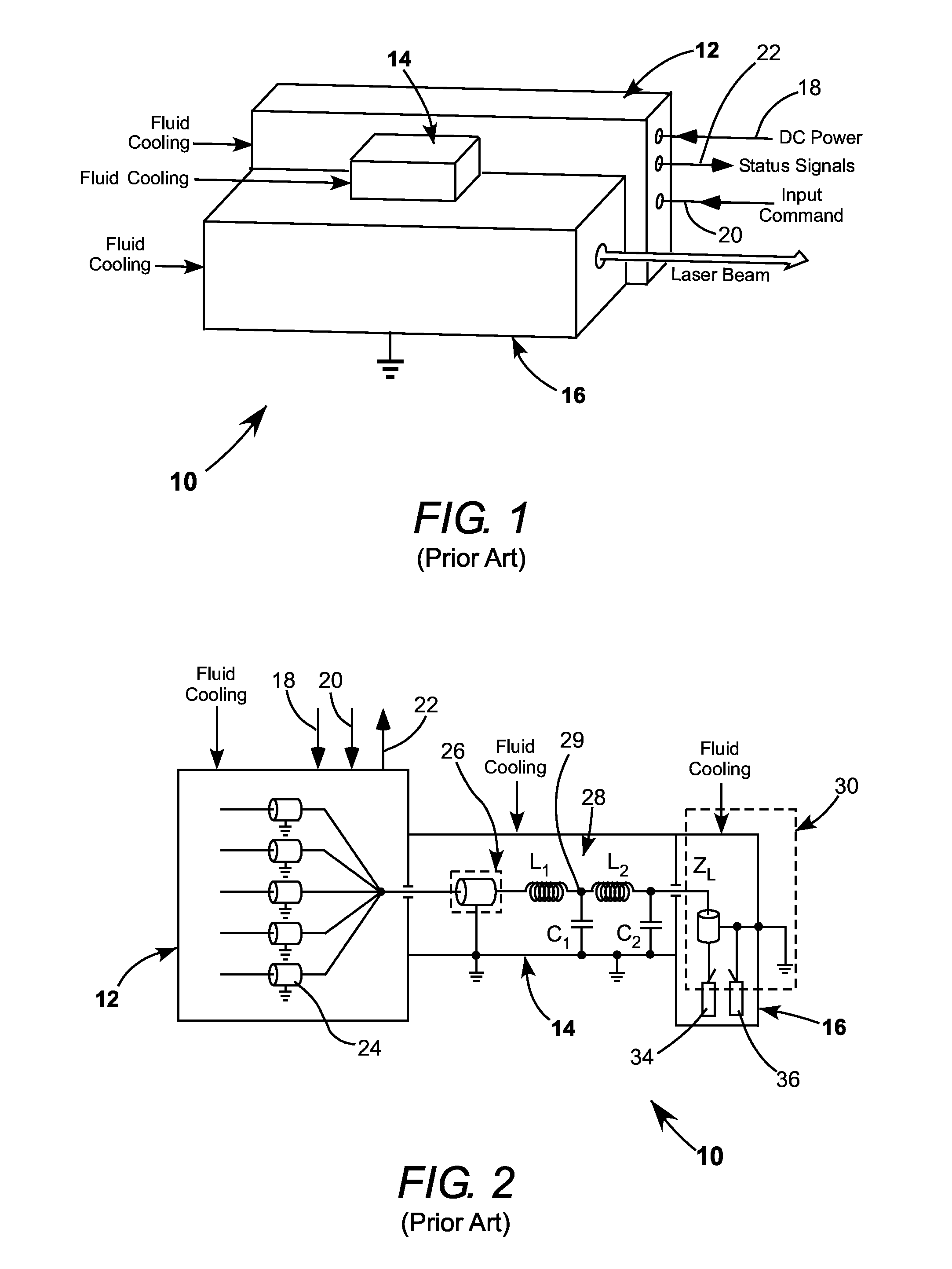
[0038]Compartment 46 is for enclosing the RFPS power supply of the laser and the impedance-matching network for the laser discharge electrodes. Accordingly this compartment combines the functions of enclosures 12 and 14 of the above discussed pri...


PUM


Abstract

A compact CO2 slab-laser is contained in a fluid cooled housing having three compartments. One compartment houses discharge electrodes and a laser resonator. Another compartment houses a radio-frequency power supply (RFPS) assembled on a fluid-cooled chill plate and an impedance-matching network. The remaining compartment houses beam-conditioning optics including a spatial filter. The housing and RFPS chill-plate are on a common coolant-fluid circuit having a single input and a single output. The spatial filter is optionally fluid-coolable on the common coolant fluid circuit.

Description

PRIORITY[0001]This application claims priority to Provisional Application No. 61 / 618,145, filed Mar. 30, 2012, the disclosure of which is incorporated herein by refenrece.TECHNICAL FIELD OF THE INVENTION[0002]The present invention relates in general to radio-frequency (RF) energized carbon dioxide (CO2) gas-discharge lasers. The invention relates in particular to commercial packaging arrangements for such lasers.DISCUSSION OF BACKGROUND ART[0003]FIG. 1 schematically illustrates a prior-art packaging arrangement 10 for a high-power CO2 slab-laser system 10. The arrangement includes three basic subsystems packaged in separate enclosures. The three subsystems are a solid-state high-power RF power supply (RFPS) in enclosure 12; an RF impedance-matching network in enclosure 14 including components required to match the output impedance of the RFPS to the input impedance of the laser-discharge; and a hermetically sealed CO2 laser tube housing 16 that contains laser-discharge electrodes in...

Claims


Application Information

Patent Timeline
Patent Type & Authority Patents(United States)
IPC IPC(8): H01S3/04
CPCH01S3/041H01S3/0315H01S3/04H01S3/005H01S3/0078G02B27/0988H01S3/02H01S3/2232H01S3/0407H01S3/097H01S3/22
Inventor NEWMAN, LEON A.PAPANIDE, ADRIANRZEWNICKI, MATHEW DAVIDHENNESSEY, JR., THOMAS V.
Owner COHERENT INC
Why Eureka
Try Eureka