Motor drive circuit and illumination apparatus

a technology of motor drive and illumination apparatus, which is applied in the direction of motor/generator/converter stopper, dynamo-electric converter control, instruments, etc., can solve the problems of reduced efficiency and life, low heat generation

Inactive Publication Date: 2014-05-27
SEMICON COMPONENTS IND LLC
View PDF16 Cites 2 Cited by
  • Summary
  • Abstract
  • Description
  • Claims
  • Application Information

AI Technical Summary

Benefits of technology

[0006]LED has a longer life as compared with an incandescent bulb, it is suitable for being used in an illumination apparatus to be installed in a place inconvenient for replacement such as a ceiling. On the other hand, the LED has lower heat generation than that of the incandescent lamp but is susceptible to heat, thereby requiring appropriate cooling using a heat sink, etc., to prevent reduction in efficiency and life.

Problems solved by technology

On the other hand, the LED has lower heat generation than that of the incandescent lamp but is susceptible to heat, thereby requiring appropriate cooling using a heat sink, etc., to prevent reduction in efficiency and life.

Method used


Image

  • Motor drive circuit and illumination apparatus
  • Motor drive circuit and illumination apparatus
  • Motor drive circuit and illumination apparatus

Examples


Embodiment Construction

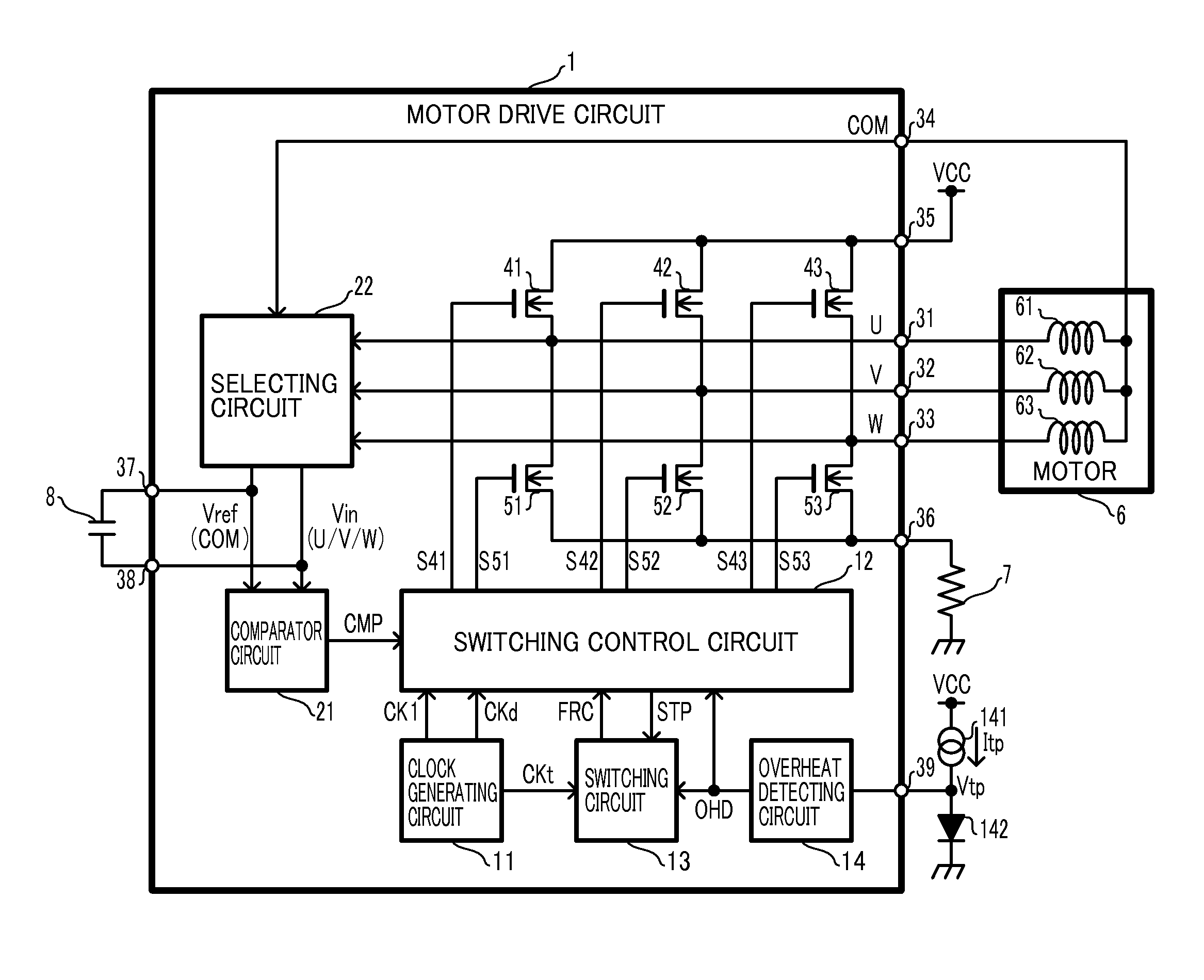
[0020]At least the following details will become apparent from descriptions of this specification and of the accompanying drawings.

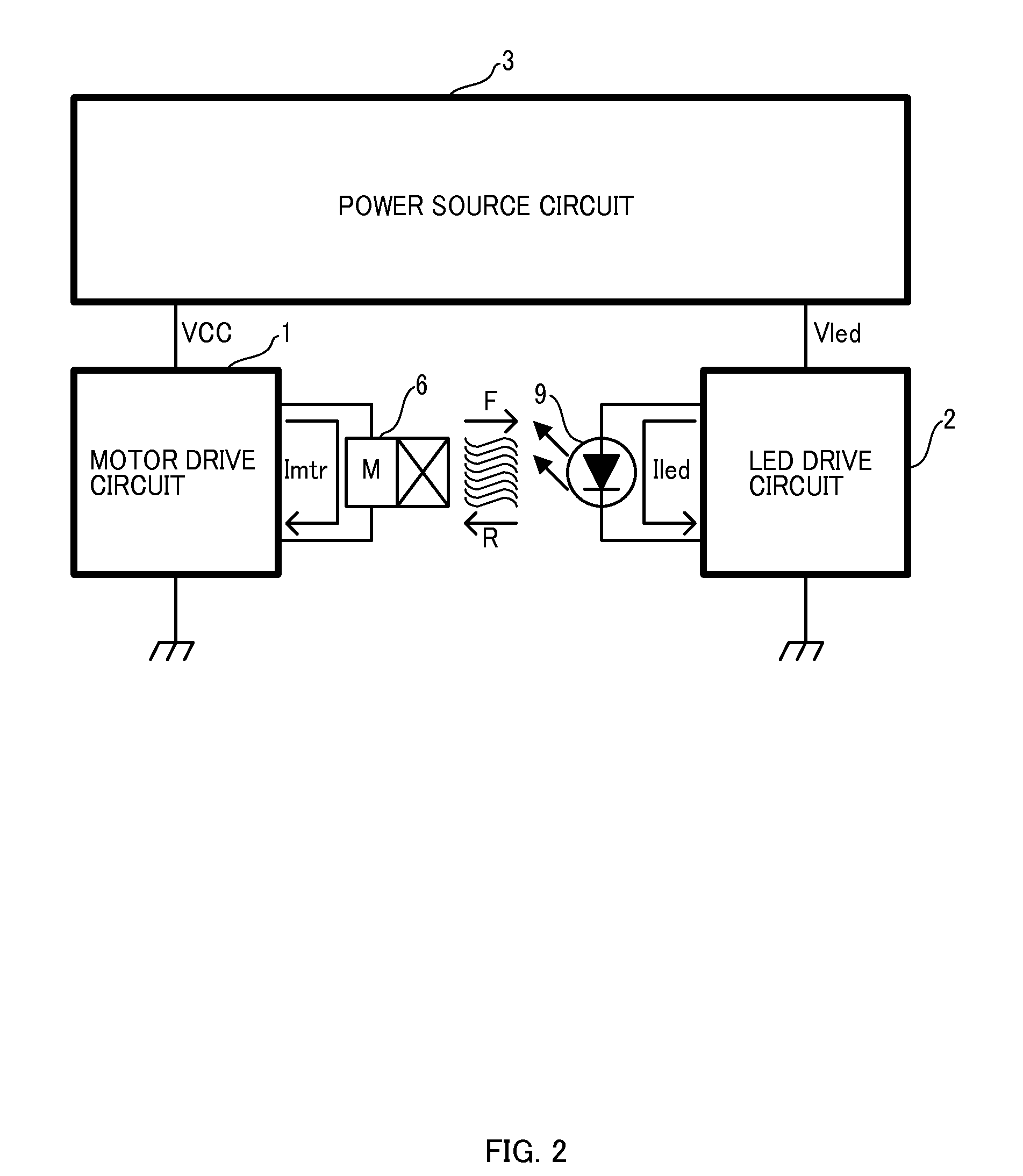
[0021]An outline will hereinafter be described of a configuration of an illumination apparatus as a whole including a motor drive circuit according to an embodiment of the present invention, which will be described later, with reference to FIG. 2. Detailed description will be given later of a configuration of a motor drive circuit 1.

[0022]The illumination apparatus shown in FIG. 2 is an illumination apparatus employing an LED as an illumination element, and includes the motor drive circuit 1, an LED drive circuit 2, a power supply circuit 3, a motor 6, and an LED 9. The motor drive circuit 1 and the LED drive circuit 2 are connected to the power supply circuit 3. Further, the motor 6 is connected to the motor drive circuit 1 and the LED 9 is connected to the LED drive circuit 2. It is assumed that the rotating shaft of the motor 6 is connected to a fan, ...


PUM


Abstract

A motor-drive circuit includes: an output transistor configured to supply a drive current to a motor for a cooling fan; a switching-control circuit configured to control switching of the output transistor so that the motor rotates in a first direction, or rotates in a second direction opposite to the first direction; and a switching circuit configured to, when a first time has elapsed since start of rotation of the motor in the first direction, cause the switching-control circuit to start switching control so that the motor stops rotating in the first direction and thereafter rotates in the second direction, and configured to, when a second time has elapsed since start of rotation of the motor in the second direction, cause the switching-control circuit to start switching control so that the motor stops rotating in the second direction and thereafter rotates in the first direction.

Description

CROSS-REFERENCE TO RELATED APPLICATION[0001]This application claims the benefit of priority to Japanese Patent Application No. 2010-068644, filed Mar. 24, 2010, of which full contents are incorporated herein by reference.BACKGROUND OF THE INVENTION[0002]1. Field of the Invention[0003]The present invention relates to a motor drive and an illumination apparatus circuit[0004]2. Description of the Related Art[0005]Recently, an LED (Light Emitting Diode) is used for an illuminating purpose as well. In particular, since the[0006]LED has a longer life as compared with an incandescent bulb, it is suitable for being used in an illumination apparatus to be installed in a place inconvenient for replacement such as a ceiling. On the other hand, the LED has lower heat generation than that of the incandescent lamp but is susceptible to heat, thereby requiring appropriate cooling using a heat sink, etc., to prevent reduction in efficiency and life.[0007]For example, Japanese Patent Laid-Open Publi...

Claims


Application Information

Patent Timeline
Patent Type & Authority Patents(United States)
IPC IPC(8): G05D11/08H02P6/06H02P6/08H02P6/22
CPCH02P6/22H02P6/003H02P6/30
Inventor YOSHITOMI, TETSUYATANABE, MASASHISUZUKI, SYUNJI
Owner SEMICON COMPONENTS IND LLC
Why Eureka
Try Eureka