System and method for sensor failure detection

a technology of image sensor and system, applied in the field of image sensor failure detection, can solve the problems of pixel row control circuit, prone to damage, row control circuit,

Active Publication Date: 2014-05-27
OMNIVISION TECH INC
View PDF1 Cites 33 Cited by
  • Summary
  • Abstract
  • Description
  • Claims
  • Application Information

AI Technical Summary

Problems solved by technology

Although traditional image sensors meet the needs of many image and video capture applications, there are drawbacks to current designs.
As another example, pixel row signal lines (e.g., transfer lines, reset lines, row-select lines, etc.), column sampling lines, and column sampling component control lines (e.g., gain amplifier control lines, analog-to-digital converter control lines, digitized pixel data storage device control lines, etc.) are prone to damage, especially those subjected to large distributed stress-causing loads.
As yet another problem, row control circuits are also prone to failure.
In the event that any of the aforementioned failures occur in a conventional image sensor, it will generally output erroneous image data to the hosting system.
Of course, a hosting system typically does not recognize the difference between erroneous image data and correct image data.
This can be particularly problematic in certain applications (i.e. integral machine vision applications) wherein the image data dictates operational tasks performed by the host system.

Method used


Image

  • System and method for sensor failure detection
  • System and method for sensor failure detection
  • System and method for sensor failure detection

Examples


Embodiment Construction

[0051]The present invention overcomes the problems associated with the prior art, by providing an image sensor that includes malfunction detection circuitry. In the following description, numerous specific details are set forth (e.g., image sensor types, pixel types, transistor types, number of pixels, etc.) in order to provide a thorough understanding of the invention. Those skilled in the art will recognize, however, that the invention may be practiced apart from these specific details. In other instances, details of well-known integrated circuit image sensor manufacturing practices (e.g., transistor forming, color filter forming, wafer singulation, semiconductor doping, etc.) and components have been omitted, so as not to unnecessarily obscure the present invention.

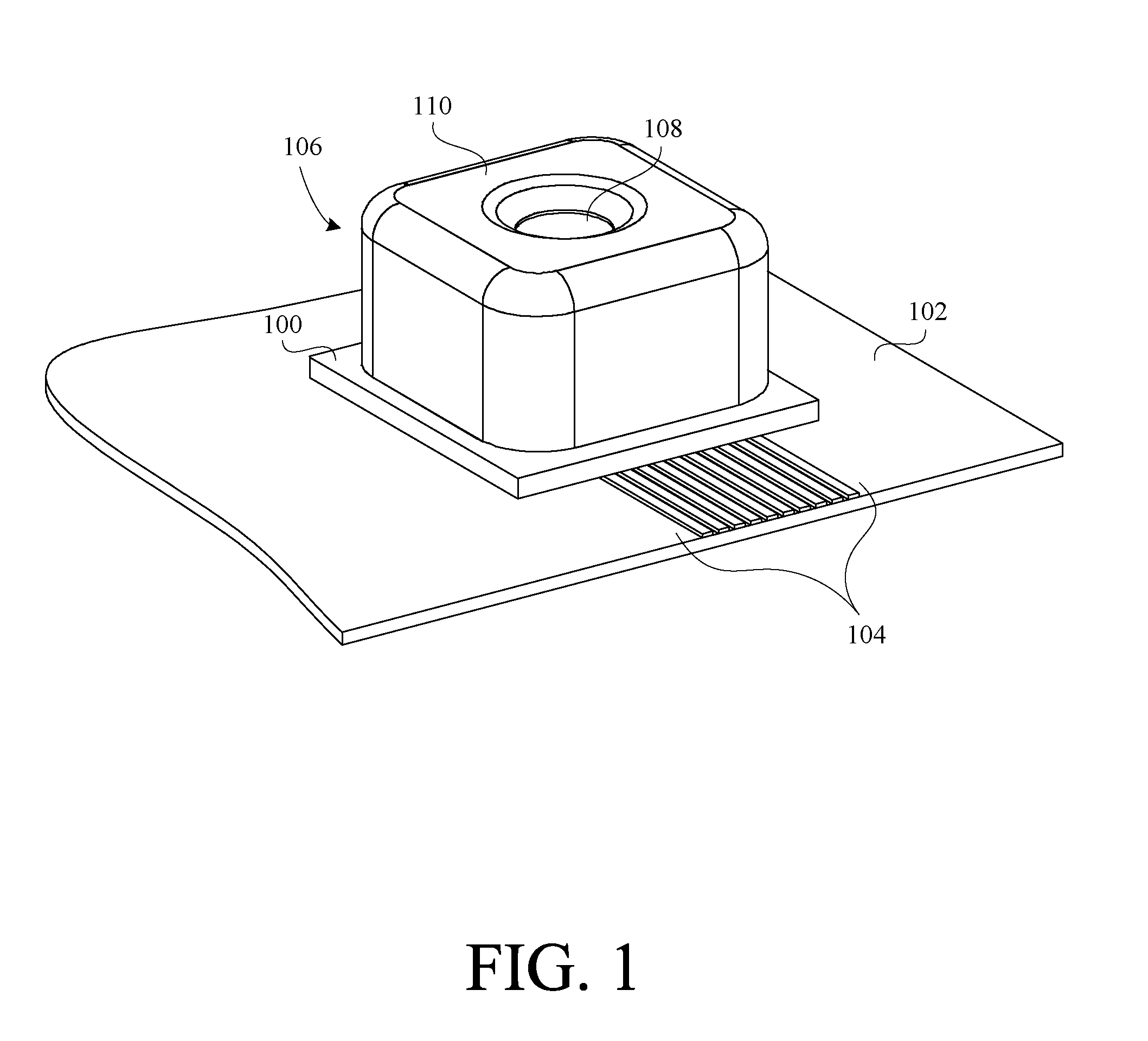
[0052]FIG. 1 is a perspective view of an image sensor 100 mounted on a portion of a printed circuit board (PCB) 102 that represents a PCB of a camera hosting device (e.g., automobile, manufacturing machine, medic devic...


PUM


Abstract

A novel image sensor includes a pixel array, a row control circuit, a test signal injection circuit, a sampling circuit, an image processing circuit, a comparison circuit, and a control circuit. In a particular embodiment, the test signal injection circuit injects test signals into the pixel array, the sampling circuit acquires pixel data from the pixel array, and the comparison circuit compares the pixel data with the test signals. If the pixel data does not correspond to the test signals, the comparison circuit outputs an error signal. Additional comparison circuits are provided to detect defects in the control circuitry of an image sensor.

Description

BACKGROUND OF THE INVENTION[0001]1. Field of the Invention[0002]This invention relates generally to image sensors, and more particularly to failure detection in image sensors.[0003]2. Description of the Background Art[0004]Electronic image sensors are commonly incorporated into a variety of devices including, for example, cell phones, computers, digital cameras, PDA's, etc. In addition to conventional user-controlled still and video camera applications, more and more image sensor applications are emerging. For example, integral machine vision applications are expanding rapidly in the automotive, manufacturing, medical, security, and defense industries. In such applications, machines typically perform certain operational tasks (e.g. collision prevention tasks) based on information (e.g. position of an object relative another object) captured by the image capture system of the machine. In order for the machine to perform the proper task associated with the particular situation, it is ...

Claims


Application Information

Patent Timeline
Patent Type & Authority Patents(United States)
IPC IPC(8): H04N5/367H04N17/00
CPCH04N5/357H04N17/002H04N5/367H04N25/68H04N25/60
Inventor JOHANSSON, ROBERTMARTINUSSEN, TORE
Owner OMNIVISION TECH INC
Why Eureka
Try Eureka