Monitoring for disturbance of optical fiber
a technology of optical fiber and physical disturbance, applied in the direction of transmission monitoring, optical waveguide device testing, instruments, etc., can solve the problems of low loss, difficult to distinguish between abnormal or “reportable, optical changes with similarities, and inability to reliably detect low loss, etc., to achieve the effect of reducing deficiencies
- Summary
- Abstract
- Description
- Claims
- Application Information
AI Technical Summary
Benefits of technology
Problems solved by technology
Method used
Image
Examples
embodiment 1
Two Launch States; Four Analyzer States
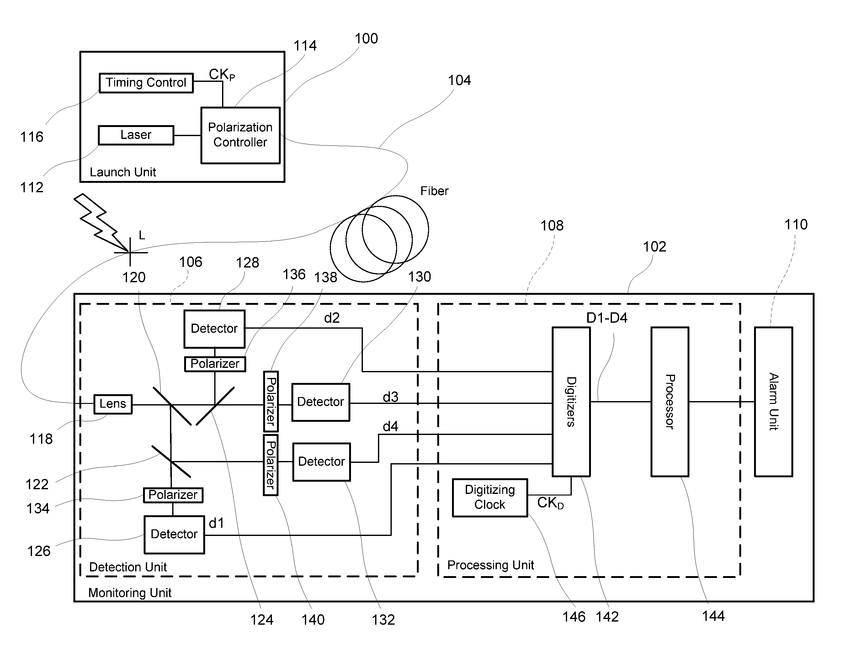
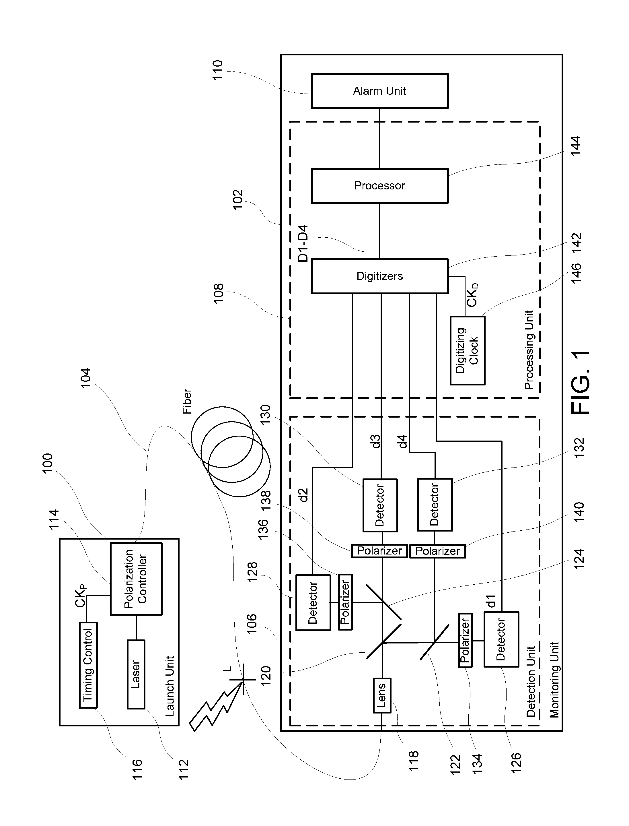
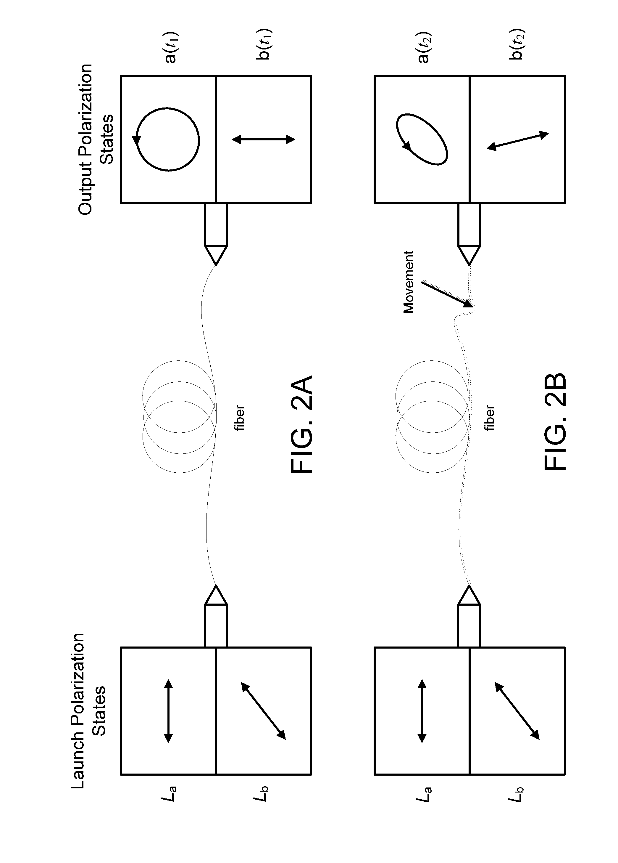
[0112]A first embodiment, a monitoring system that uses two launch states and four analyzer states, will be described by way of example with reference to FIGS. 1 to 15. As shown in FIG. 1, a launch unit 100 and a monitoring unit 102 are coupled to first and second ends, respectively, of a length of optical fiber 104 which might be from a few meters to more than 40 km long. In the following description, the first end and second end may also be described as proximal and distal, respectively, with respect to the launch unit 100. The first / proximal end will be deemed to be “upstream” and the second / distal end “downstream” even though there may be counter-propagating reflected light and regardless of whether the two ends are physically remote from each other, for example as ends of an optical cable in an optical communications network, or physically co-located, for example where the length of optical fiber comprises two individual fibers “looped bac...
embodiment 2
Two Launch States; Two Analyzer States Plus an Unpolarized Detector
[0182]A second embodiment, which uses two launch polarization states and two polarized detection states plus a polarization-insensitive detector, will be described with reference to FIG. 16. It illustrates the advantage of reduced fading, and the advantage of liberty in selecting the polarization states that are launched into the fiber and selected by the detectors.
[0183]In FIG. 16, a launch unit 100 and a monitoring unit 102 are shown coupled to proximal and distal ends, respectively, of an optical fiber 104 which might be from a few meters long to more than 50 km. Light in two different states of polarization (SOP), launched into the proximal end of fiber 104 by launch unit 100, travels through the fiber 104 and is received at the distal end by the monitoring unit 102 and analyzed for changes consistent with a physical disturbance of the fiber 104 indicative of an intrusion attempt somewhere along its length. Such ...
embodiment 3
Two Launch States; Two Analyzer States
[0210]A third embodiment of the hardware is illustrated in FIG. 17. It is similar to the embodiment described above in connection with FIG. 16, except for three specific differences with advantages that can reduce the cost in particular applications, and that can mostly be implemented independently of each other in different combinations to suit a particular application.
[0211]A first difference is that the synchronizer 146 that tracks the polarization modulation frequency and phase is eliminated, and replaced by a direct connection of the timing control unit 116 to the digitizer block 142. This is especially suitable for applications where the fiber 104 is short, or where it is long but looped back, so that the launch unit 100 and the monitoring unit 102 are close together and a direct connection is easy. Also, the timing control unit 116 no longer causes periodic higher-intensity pulses of the laser 112 to act as synchronizing markers, and the ...
PUM
| Property | Measurement | Unit |
|---|---|---|
| length | aaaaa | aaaaa |
| frequency | aaaaa | aaaaa |
| wait time | aaaaa | aaaaa |
Abstract
Description
Claims
Application Information
 - R&D
- Intellectual Property
- Life Sciences
- Materials
- Tech Scout
- Unparalleled Data Quality
- Higher Quality Content
- 60% Fewer Hallucinations
Browse by: Latest US Patents, China's latest patents, Technical Efficacy Thesaurus, Application Domain, Technology Topic, Popular Technical Reports.
© 2025 PatSnap. All rights reserved.Legal|Privacy policy|Modern Slavery Act Transparency Statement|Sitemap|About US| Contact US: help@patsnap.com


