Lossy triphase low-pass filter

a low-pass filter and triphase technology, applied in the field of lossy triphase low-pass filter, can solve the problems of increased power loss, increased loss, and less effective attenuation of low-pass filter with little resonant excitation, so as to reduce the current load on the diodes, reduce the price of attenuation elements, and reduce the current load

Active Publication Date: 2014-06-03
SIEMENS AG
View PDF17 Cites 2 Cited by
  • Summary
  • Abstract
  • Description
  • Claims
  • Application Information

AI Technical Summary

Benefits of technology

[0016]In another advantageous embodiment of the alternative embodiment of the lossy triphase low-pass filter according to the invention, a switched-mode power supply is provided as the load in the short-circuit current path of the six-pulse bridge circuit of the diodes as the attenuation element, which switched-mode power supply is used to feed the attenuation energy produced back into an intermediate circuit of a frequency converter, to the outputs of which this lossy low-pass filter is connected. The output voltage of the bridge circuit can be controlled to a predetermined value using the switched-mode power supply as the load in the DC-voltage-side short-circuit current path of the six-pulse bridge circuit of the diodes as attenuation elements of the low-pass filter. This makes it possible to set desired attenuation.
[0017]In another advantageous embodiment of the alternative embodiment of the lossy triphase low-pass filter according to the invention, a filter, in particular a band-stop filter, is connected upstream of the six-pulse bridge circuit of the diodes as the attenuation element of the low-pass filter. This limits the current in the six-pulse diode bridge circuit to frequency components which are in the range of the resonant frequency of the low-pass filter. This has the advantage that only those frequency components of the capacitor current of the lossy low-pass filter which may rise to resonance are attenuated. This considerably reduces the current load on the diodes of the six-pulse diode bridge circuit, as a result of which diodes with a lower current load can be used. Not only the space requirement but also the price of the attenuation elements therefore decreases.

Problems solved by technology

However, an increased power loss must be expected with these attenuated low-pass filters.
The use of non-reactive resistors as attenuation elements 32 has the disadvantage that attenuation is less effective with little resonant excitation of the low-pass filter 30.
These losses become greater, the greater the intended attenuation effect.

Method used


Image

  • Lossy triphase low-pass filter
  • Lossy triphase low-pass filter
  • Lossy triphase low-pass filter

Examples


Embodiment Construction

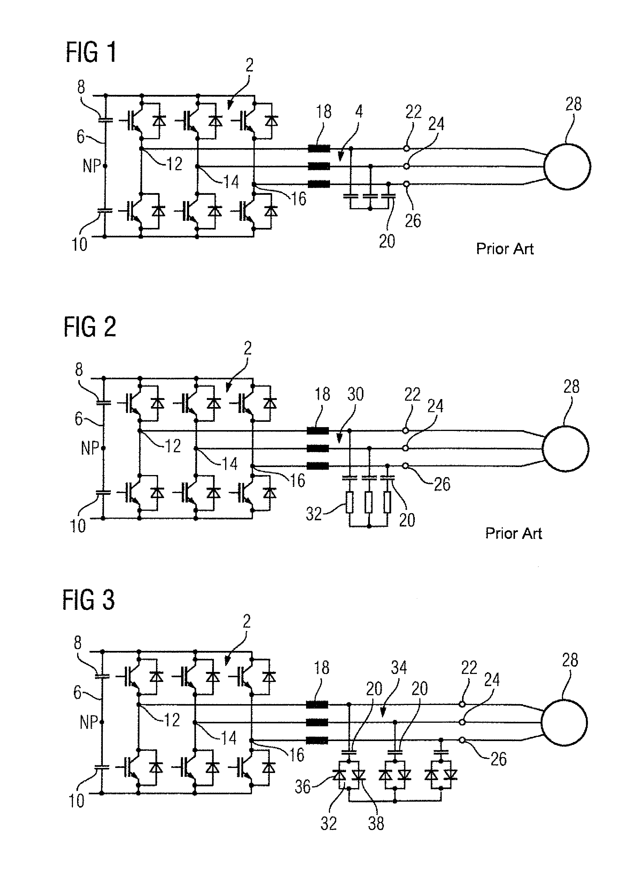
[0024]FIG. 3 shows a first embodiment of a lossy triphase low-pass filter 34 according to the invention. This lossy triphase low-pass filter 34 is likewise linked, on the input side, to output-side connections 12, 14 and 16 of the load-side power converter 2 of a frequency converter. A triphase load 28 is connected to the output terminals 22, 24 and 26 of this low-pass filter 34. This embodiment of the lossy triphase low-pass filter 34 according to the invention differs from the embodiment of a known lossy triphase low-pass filter 30 according to FIG. 2 in that two diodes 36 and 38 which are reverse-connected in parallel are respectively provided as the attenuation element 32 instead of a non-reactive resistor. As a result of the use of diodes 36 and 38 which are reverse-connected in parallel as attenuation elements 32, considerable attenuation already occurs when a small filter current flows. As in the known embodiment with resistors as attenuation elements 32, attenuation is likew...


PUM


Abstract

The invention relates to a lossy triphase low-pass filter having a filter choke, a filter capacitor, and an attenuation element per phase of said the low-pass filter, wherein one filter capacitor and one attenuation element each are electrically connected in series. Two diodes are provided as attenuation elements, which are electrically connected to each other in an anti-parallel manner. In this manner a lossy triphase low-pass filter is obtained, the power loss of which is significantly reduced without any loss of the attenuation effect.

Description

CROSS-REFERENCES TO RELATED APPLICATIONS[0001]This application is the U.S. National Stage of International Application No. PCT / EP2009 / 053849, filed Apr. 1, 2009, which designated the United States and has been published as International Publication No. WO 2009 / 146961 and which claims the priority of German Patent Application, Serial No. 10 2008 026 869.0, filed Jun. 5, 2008, pursuant to 35 U.S.C. 119(a)-(d).BACKGROUND OF THE INVENTION[0002]The invention relates to a lossy triphase low-pass filter.[0003]Commercially available voltage intermediate-circuit converters which are also referred to as frequency converters very often have a so-called output sinusoidal filter on the load side. This output sinusoidal filter is intended to be used to filter out the high-frequency components of each pulsed output voltage of this frequency converter in such a manner that only a fundamental voltage remains at a load, in particular an electric motor, connected to the load-side connections of the fr...

Claims


Application Information

Patent Timeline
Patent Type & Authority Patents(United States)
IPC IPC(8): H02M1/12
CPCH03H1/00H02M1/126
Inventor SCHIERLING, HUBERTWEIS, BENNO
Owner SIEMENS AG
Why Eureka
Try Eureka