
Reflection type blank masks, methods of fabricating the same, and methods of fabricating reflection type photo masks using the same

a blank mask and reflection type technology, applied in the field of photo masks, can solve the problems of limiting the realization of fine patterns with the photolithography process utilizing ultraviolet, euv lithography process may be affected by substrate defects, and it is difficult to fabricate blank masks without defects, so as to minimize the number of defects overlapped with the circuit pattern

Active Publication Date: 2014-06-10
SK HYNIX INC
View PDF1 Cites 0 Cited by
  • Summary
  • Abstract
  • Description
  • Claims
  • Application Information

AI Technical Summary

Benefits of technology

The patent text describes a method of making a reflection type photo mask. The method involves adding a layer of reflection to the mask, creating a mark on the reflection layer, inspecting the layer for defects and collecting data on the defects, and then adding absorption layer patterns to the layer after inspecting it. These absorption layer patterns will be the basis of the circuit patterns that will be formed on a wafer. The method is designed to minimize defects that may affect the circuit patterns.

Problems solved by technology

Thus, there may be some limitations in realizing the fine patterns with a photolithography process utilizing ultraviolet (UV) rays.
There are many issues in the development of the EUV lithography process.
For example, the EUV lithography process may be affected by substrate defects of the reflection type masks used in the EUV lithography process.
In particular, it may be difficult to fabricate blank masks without any defects because the laminated reflection layer of the EUV mask is formed by stacking a plurality of layers, for example, about eighty layers of molybdenum / silicon.
That is, the substrate defects may degrade the quality of the reflection type masks.

Method used


Image

  • Reflection type blank masks, methods of fabricating the same, and methods of fabricating reflection type photo masks using the same
  • Reflection type blank masks, methods of fabricating the same, and methods of fabricating reflection type photo masks using the same
  • Reflection type blank masks, methods of fabricating the same, and methods of fabricating reflection type photo masks using the same

Examples


Embodiment Construction

[0017]Various embodiments will be described more fully hereinafter with reference to the accompanying drawings. In explanations of the various embodiments, the same or corresponding elements may be denoted by the same reference numerals or the same reference designators. To avoid duplicate explanation, descriptions to the same elements as set forth in the previous embodiment may be omitted or briefly mentioned in each embodiment.

[0018]The figures are provided to allow those having ordinary skill in the art to understand the scope of the embodiments of the disclosure. The present invention may, however, be embodied in different forms and should not be construed as limited to the embodiments set forth herein. Rather, these embodiments are provided so that this disclosure will be thorough and complete, and will fully convey the scope of the present invention to those skilled in the art.

[0019]Meanwhile, it may be understood that when one element, such as a layer, is referred to as being...


PUM

PropertyMeasurementUnit
thicknessaaaaaaaaaa
wave lengthaaaaaaaaaa
reflectivityaaaaaaaaaa

Abstract

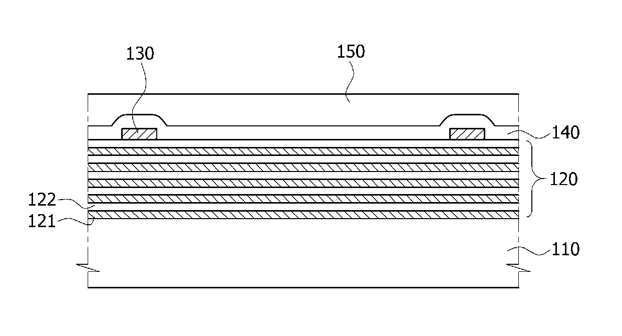
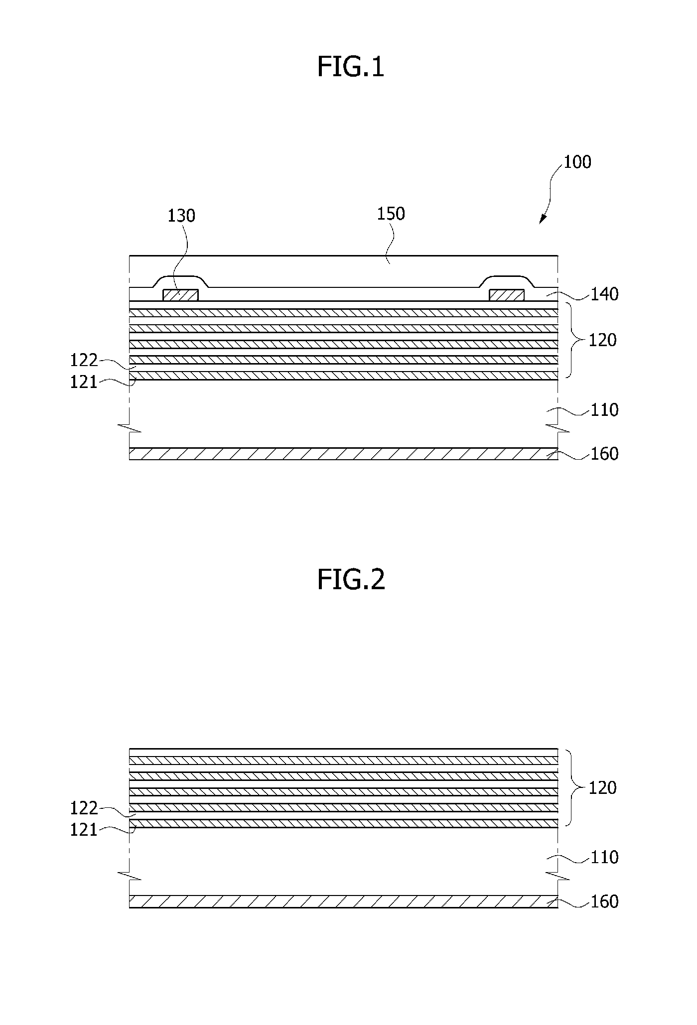
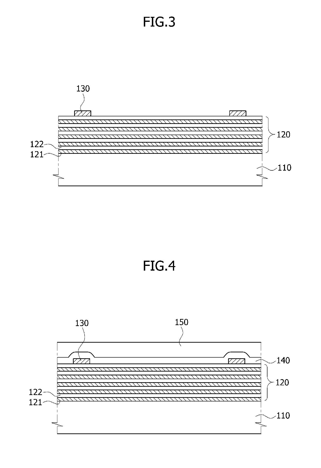
Reflection type blank masks are provided. The blank mask includes a substrate, a reflection layer substantially on the substrate, at least one fiducial mark substantially on the reflection layer, an absorption layer substantially on the at least one fiducial mark and the reflection layer, and a resist layer substantially on the absorption layer.

Description

CROSS-REFERENCES TO RELATED APPLICATIONS[0001]The present application claims priority under 35 U.S.C 119(a) to Korean Application No. 10-2012-0060242, filed on Jun. 5, 2012, in the Korean intellectual property Office, which is incorporated herein by reference in its entirety.BACKGROUND[0002]1. Technical Field[0003]Various embodiments of the present disclosure generally relate to photo masks used in fabrication of semiconductor devices, and to reflection type blank masks, methods of fabricating the same, and methods of fabricating reflection type photo masks using the same.[0004]2. Related Art[0005]As semiconductor devices become more highly integrated, sizes of circuit patterns constituting the semiconductor devices have been continuously reduced. Thus, there may be some limitations in realizing the fine patterns with a photolithography process utilizing ultraviolet (UV) rays. Accordingly, an extreme ultraviolet (EUV) lithography process has been proposed to form the fine patterns o...

Claims


Application Information

Patent Timeline
Patent Type & Authority Patents(United States)
IPC IPC(8): G03F1/24G03F1/42
CPCG03F1/24G03F1/42G03F1/38G03F1/52G03F1/54
Inventor KIM, YONG DAENAM, BYUNG HO
Owner SK HYNIX INC
Learn More