Method of chucking a tool or a workpiece and apparatus for carrying out the method

a technology of clamping and workpieces, applied in the direction of locking applications, manufacturing tools, attachable milling devices, etc., can solve the problems of affecting the accuracy of clamping force, and requiring motor torque for controlling the achieved clamping for

Inactive Publication Date: 2014-06-17
ROHM GMBH
View PDF13 Cites 13 Cited by
  • Summary
  • Abstract
  • Description
  • Claims
  • Application Information

AI Technical Summary

Benefits of technology

[0004]The object of the invention, therefore, is to provide a method by means of which the above-referenced problems may be avoid

Problems solved by technology

In practice, use of the electric actuator disclosed in DE 10 2006 015 918 has resulted in issues with regard to stroke control that are in need of improvement, since the analog length measurement via the sensor that is used is relatively inaccurat

Method used


Image

  • Method of chucking a tool or a workpiece and apparatus for carrying out the method
  • Method of chucking a tool or a workpiece and apparatus for carrying out the method
  • Method of chucking a tool or a workpiece and apparatus for carrying out the method

Examples


Embodiment Construction

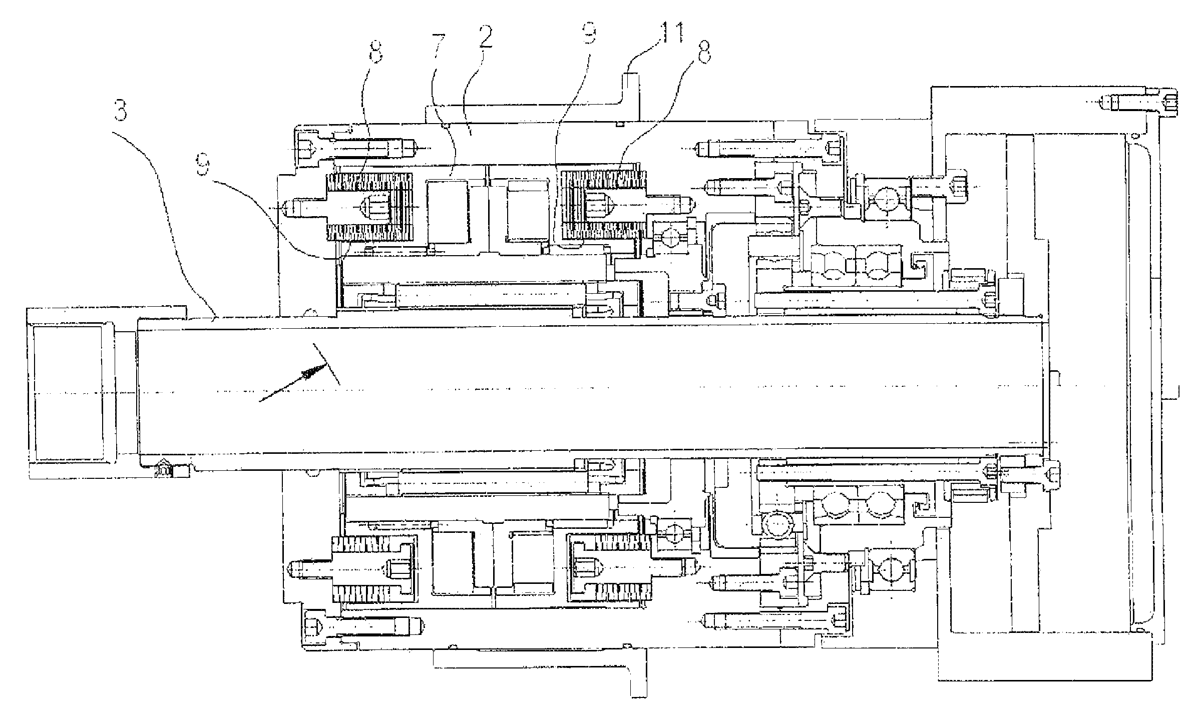
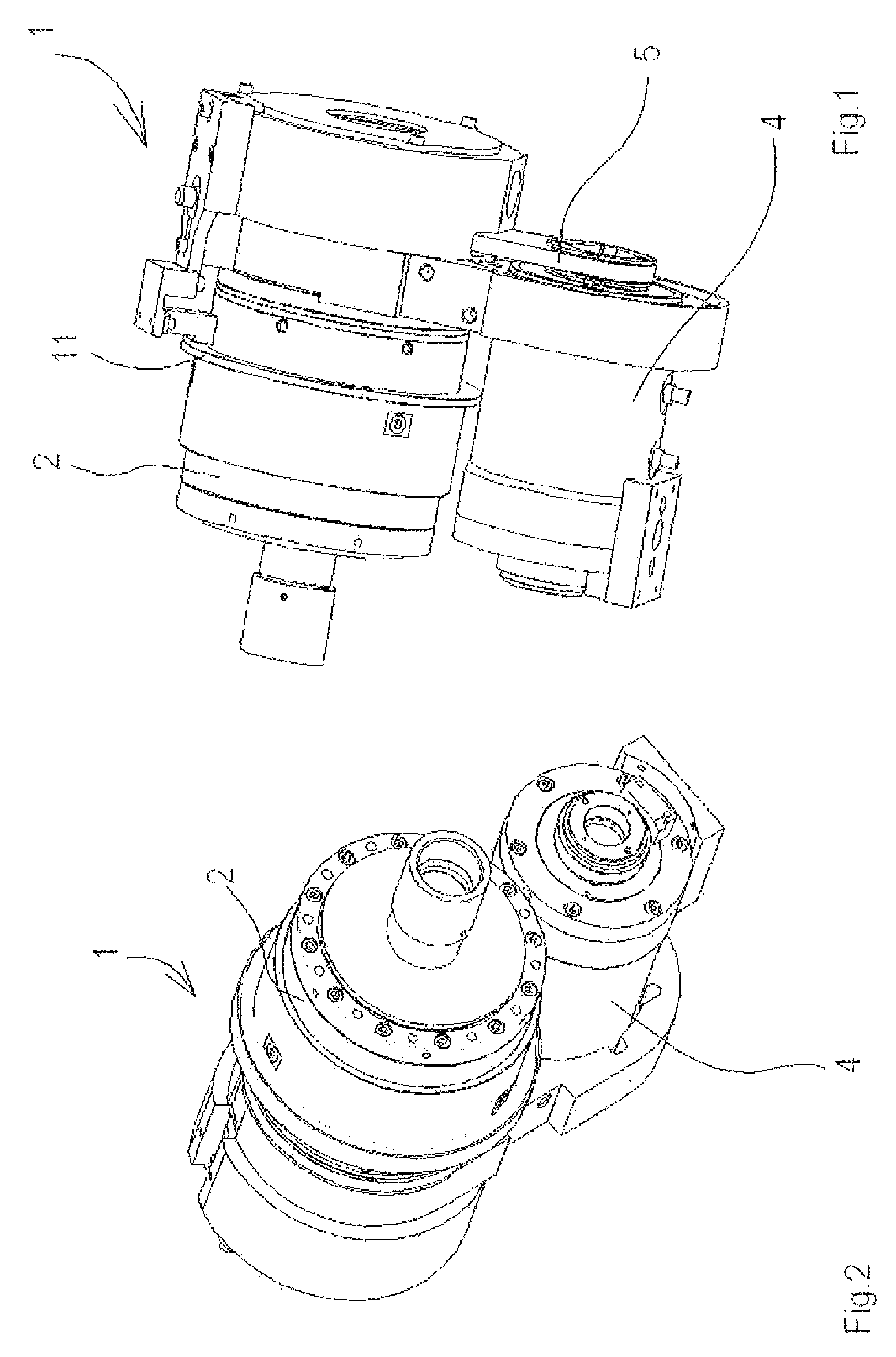
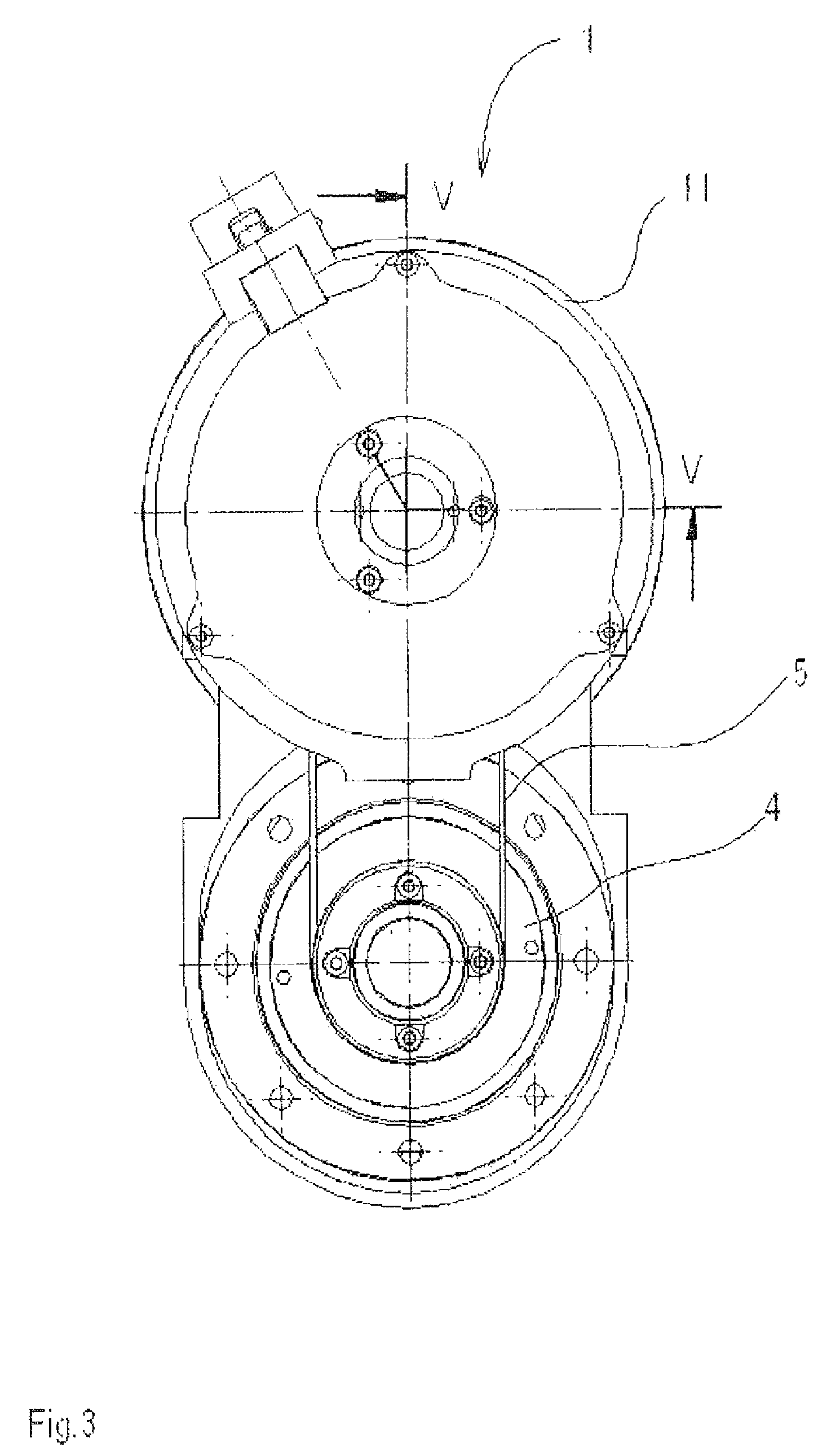
[0021]The drawing shows an electric actuator 1 used to move the jaws of a chuck attached to a machine tool, and to continuously and safely clamp a workpiece or tool during a clamping operation. The electric actuator 1 has a housing 2 for attachment to a machine-tool work spindle and in which an axially displaceable threaded spindle 3 for moving the chuck jaws is mounted. The electric actuator 1 also includes an electric servomotor 4 mounted on the side of the housing 2. A gear-type harmonic drive is connected between the electric servomotor 4 and the threaded spindle 3, the rotor of the servomotor 4 being connected via a belt 5 to a drive pulley 6 connected to the wave generator of the harmonic drive. The circular spline of the harmonic drive is connected to the housing 2, while the flexspline of the harmonic drive drives the threaded spindle 3. In the embodiment illustrated in the drawing, the threaded spindle 3 is moved by a spindle nut 7 engaged axially between two spring stacks ...


PUM

PropertyMeasurementUnit
Lengthaaaaaaaaaa
Lengthaaaaaaaaaa

Abstract

The invention relates to a method of clamping a tool or a workpiece, using an electric actuator (1) having a housing (2) attached to a work spindle of a machine tool and in which a threaded spindle (3) for moving jaws of a chuck is axially displaceable, and an electric servomotor (4) having a rotor connected with a drive wheel (6) that moves a nut (7) on the threaded spindle (3), a first sensor being associated with the threaded spindle (3) for detecting the axial position thereof, and a second sensor being associated with the spindle nut (7) for detecting the axial position thereof, and including the method step of determining the position of the threaded spindle (3) by the first sensor when a slight axial force occurs due to contact of the clamping jaws with the tool or the workpiece, and continued movement of the spindle nut (7) until a specified sensor difference (12) between the first sensor and the second sensor is determined by the second sensor. The invention further relates to an apparatus for carrying out the method.

Description

CROSS REFERENCE TO RELATED APPLICATIONS[0001]This application is the US-national stage of PCT application PCT / DE2010 / 075068, filed 29 Jul. 2010 and claiming the priority of German patent application 102009044167.0 itself filed 2 Oct. 2009.FIELD OF THE INVENTION[0002]The invention is a method of clamping a tool or a workpiece, using an electric actuator having a housing attached to the work spindle of a machine tool, and in which is mounted an axially displaceable threaded spindle for moving the clamping jaws of a chuck, and an electric servomotor whose rotor is in drive connection with a drive wheel that moves the spindle nut of the threaded spindle, a first sensor being associated with the threaded spindle for detecting the axial position thereof, and a second sensor being associated with the spindle nut for detecting the axial position thereof, and including the method step of determining the position of the threaded spindle by means of the first sensor when a slight axial force o...

Claims


Application Information

Patent Timeline
IPC IPC(8): B23P21/00B23Q15/00
CPCB23B2260/062B23B31/28B23B2260/128Y10T29/53087Y10T279/21Y10T29/4978Y10T279/275Y10T29/49771Y10T29/49998Y10T409/30952B23B2260/136B23Q17/003E05B77/06E05B79/20E05B85/16B23Q16/00B23Q17/00
Inventor HANGLEITER, EUGENSCHENK, PETER
Owner ROHM GMBH
Why Eureka
Try Eureka