Orthogonal acceleration time-of-flight spectrometer having steady potential and variable potential transport regions

a time-of-flight spectrometer and steady potential technology, applied in mass spectrometers, stability-of-path spectrometers, separation processes, etc., can solve the problems of low efficiency of ion utilization, ion loss, and inability to detect ion streams not accelerated by detectors, so as to achieve efficient estimation of the structure of precursor ions

Active Publication Date: 2014-06-17
JEOL LTD
View PDF21 Cites 8 Cited by
  • Summary
  • Abstract
  • Description
  • Claims
  • Application Information

AI Technical Summary

Benefits of technology

[0014]Therefore, in the time-of-flight (TOF) mass spectrometer according to the present invention, ions can have a smaller distribution width temporally and spatially at the acceleration timing (acceleration starting point) in the second direction than in the prior art TOF mass spectrometer not having such a variable potential region. Therefore, ions having masses lying in a wider range of mass-to-charge ratios can be detected with a single acceleration. In consequence, a TOF mass spectrometer, according to the present invention, makes it possible to achieve higher sensitivity and higher throughput for ions having masses lying in a wider range of mass-to-charge ratios.
[0030]In this TOF mass spectrometer, the range of mass-to-charge ratios of ions that can be detected is wide. Product ions of various mass-to-charge ratios can be detected at a time. Consequently, the structure of the precursor ions can be estimated efficiently.

Problems solved by technology

However, the oa-TOFMS and QqTOFMS have the problem that their efficiency of utilization of ions is low.
That is, only a part of the ion stream continuously entering the orthogonal acceleration region of the TOF mass analyzer is accelerated and so ion streams not accelerated cannot be detected by the detector.
This results in ion loss.
The problem is that the other ions cannot be detected.
U.S. Pat. No. 5,689,111, a method of increasing the efficiency of utilization of ions by connecting an ion trap to an oa-TOFMS is proposed but this method suffers from a problem similar to the problem with the method of the Chernushevich et al. patent.
The convergence is impossible with a 2D ion trap having a larger trap capacity.

Method used


Image

  • Orthogonal acceleration time-of-flight spectrometer having steady potential and variable potential transport regions
  • Orthogonal acceleration time-of-flight spectrometer having steady potential and variable potential transport regions
  • Orthogonal acceleration time-of-flight spectrometer having steady potential and variable potential transport regions

Examples


first embodiment

1. First Embodiment

[0040](1) Structure

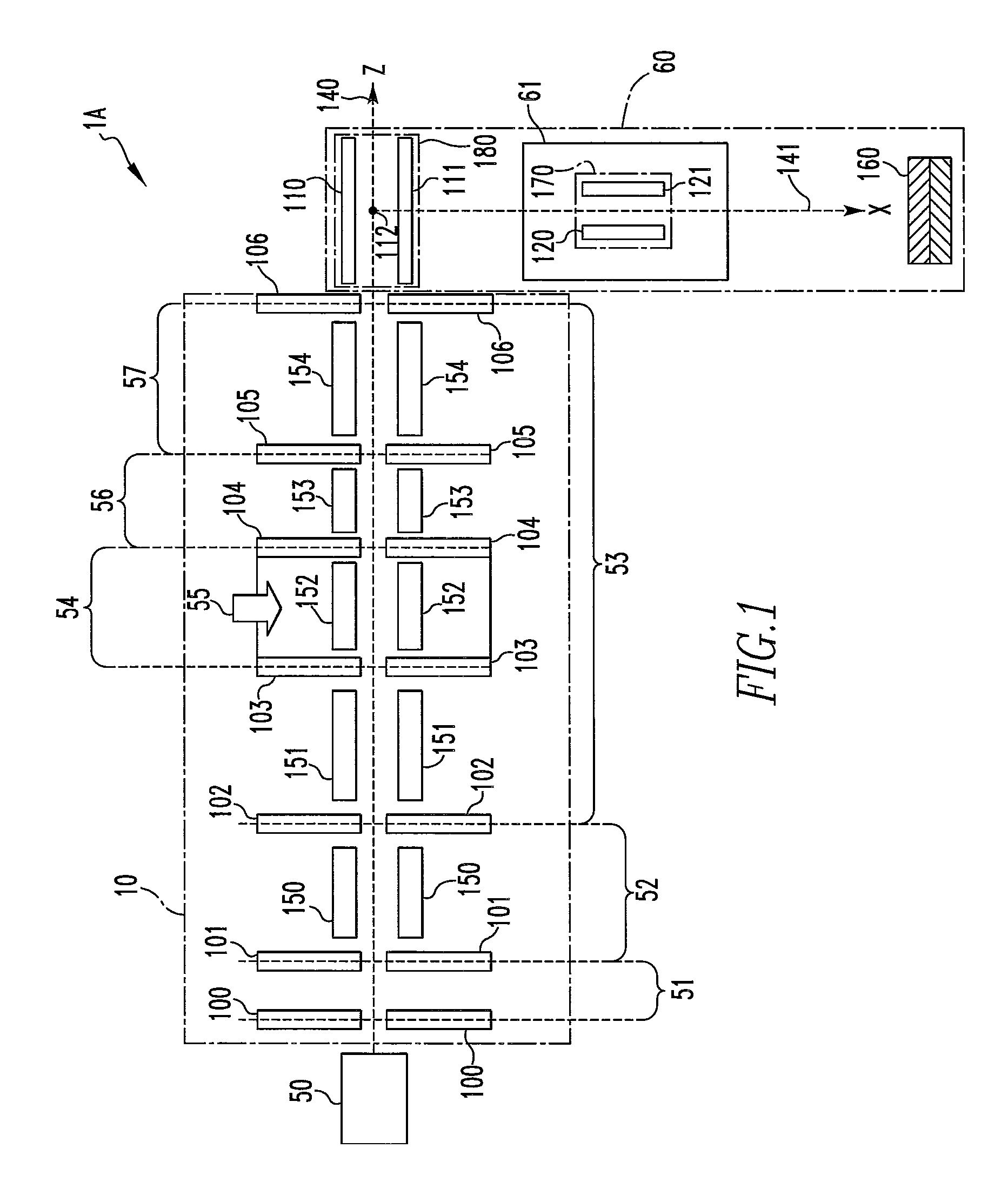
[0041]The structure of a time-of-flight (TOF) mass spectrometer according to a first embodiment of the present invention is first described. FIG. 1, which is a schematic vertical cross section of the TOF mass spectrometer, shows the structure of the spectrometer of the first embodiment.

[0042]Referring to FIG. 1, a time-of-flight (TOF) mass spectrometer according to the first embodiment of the invention is generally indicated by reference numeral 1A and configured including an ion transport region 10 and a TOF mass analyzer 60. The spectrometer 1A may also be configured including an ion source 50.

[0043]The ion source 50 ionizes samples by a given method. For example, the ion source 50 can be realized as an atmospheric-pressure continuous ion source that continuously creates ions by an atmospheric-pressure ionization (API) method such as ESI.

[0044]The ion transport region 10 includes a skimmer electrode 100 and another electrode 101 located behind...

second embodiment

2. Second Embodiment

[0096](1) Structure

[0097]FIG. 4 is a schematic vertical cross section of a time-of-flight (TOF) mass spectrometer according to a second embodiment of the invention, showing the structure of the spectrometer. In both FIGS. 1 and 4, like components are indicated by like reference numerals.

[0098]As shown in FIG. 4, the TOF mass spectrometer according to the second embodiment is generally indicated by reference numeral 1B and similar to the TOF mass spectrometer 1A according to the first embodiment except that the deflector 170 is omitted. Therefore, description of the structure of the spectrometer 1B is omitted. The difference of the spectrometer 1B with the spectrometer 1A is that the axial voltage in the multipole ion guide 153 and the voltages applied on the electrode 106, the pushout electrode 110 of the orthogonal acceleration region 180, and the extraction electrode 111 are different as described below.

[0099](2) Operation

[0100]In the following description, it ...

third embodiment

3. Third Embodiment

[0130](1) Structure

[0131]FIG. 7 is a schematic vertical cross section of a time-of-flight (TOF) mass spectrometer according to a third embodiment of the invention, showing the structure of the spectrometer. In FIGS. 1 and 7, like components are indicated by like reference numerals.

[0132]As shown in FIG. 7, the TOF mass spectrometer according to the third embodiment is generally indicated by 1C and similar to the TOF mass spectrometer 1A according to the first embodiment except that the electrode 102 and quadrupole mass filter 151 are omitted and that the collision cell 54 has been replaced by an ion storage device or region 58.

[0133]The ion storage device 58 is identical in structure with the collision cell 54 of the TOF mass spectrometer 1A. The storage device 58 acts as the ion storage region of the present invention.

[0134]In this way, the TOF mass spectrometer 1C is built as an orthogonal acceleration TOF mass spectrometer (oa-TOFMS). The spectrometer 1C is sim...


PUM


Abstract

A time-of-flight mass spectrometer has an ion transport region and a time-of-flight (TOF) mass analyzer. The ion transport region includes a collision cell (ion storage region), a steady potential region, and a variable potential region such that the difference in potential between the steady potential region and the variable potential region when ions passed through the steady potential region enter the steady potential region increases with increasing mass-to-charge ratio of ions. The mass analyzer causes the ions transported via the transport region to be accelerated along another optical axis at a given acceleration timing and guides the ions toward a detector.

Description

BACKGROUND OF THE INVENTION[0001]1. Field of the Invention[0002]The present invention relates to a time-of-flight mass spectrometer.[0003]2. Description of Related Art[0004]It is important to accurately measure the masses of ions created by an atmospheric-pressure ionization (API) technique such as electrospray ionization (ESI) or atmospheric-pressure chemical ionization (APCI) in identifying proteins and metabolic substances. Mass spectrometry relying on a time-of-flight mass spectrometer (TOFMS) can realize both high measurement accuracy and high throughput and so this spectrometry is a promising candidate for the used technique in such applications. Where a TOFMS is interfaced to an atmospheric-pressure ion source that generates ions by such an ionization method, the difference in degree of vacuum between them is as high as about 10 orders of magnitude. Therefore, a differential pumping chamber is mounted as an interface. In the atmospheric-pressure ion source, ionization occurs ...

Claims


Application Information

Patent Timeline
Patent Type & Authority Patents(United States)
IPC IPC(8): H01J49/40H01J49/42H01J49/00
CPCH01J49/0031H01J49/401H01J49/427
Inventor KOU, JUNKEI
Owner JEOL LTD
Why Eureka
Try Eureka