Scanning light field camera and display

a light field camera and light field technology, applied in the field of high-fidelity light field displays, cameras, two-way displays, can solve the problems of unsuitable display applications that demand realism, unsuitable for display applications that require realism, and limited size and resolution of practical holographic displays, and achieve the effect of rapid scan ra

Active Publication Date: 2014-06-17
VERGENT RES PTY LTD
View PDF20 Cites 68 Cited by
  • Summary
  • Abstract
  • Description
  • Claims
  • Application Information

AI Technical Summary

Benefits of technology

[0011]Persistence of vision, combined with a sufficiently rapid scan rate, allows a viewer to perceive the scanned beams as a continuous optical light field.
[0012]The appropriate focus of each beam ensures that the viewer perceives smooth parallax both between and within beams, and experiences consistent vergence and accommodation cues.
[0014]Oscillating the display surface allows incomplete coverage of the display surface by the exit pupils of the display elements to be improved.

Problems solved by technology

Although an optical light field is continuous, for practical manipulation it is band-limited and sampled, i.e. at a discrete set of points on the bounding surface and for a discrete set of ray directions.
However, volumetric displays suffer from two major drawbacks: the reconstructed scene is confined to the volume of the display, and the entire scene is semi-transparent (making it unsuitable for display applications that demand realism).
Practical holographic displays suffer from limited size and resolution, and typically only support horizontal parallax in current implementations [Schwerdtner06, Yaras10, Barabas11].
Typical multiview autostereoscopic displays provide a limited number of views, so don't support motion parallax.
However, they do not reconstruct even nominally correct optical light fields.

Method used


Image

  • Scanning light field camera and display
  • Scanning light field camera and display
  • Scanning light field camera and display

Examples


Embodiment Construction

Light Field Parameterization

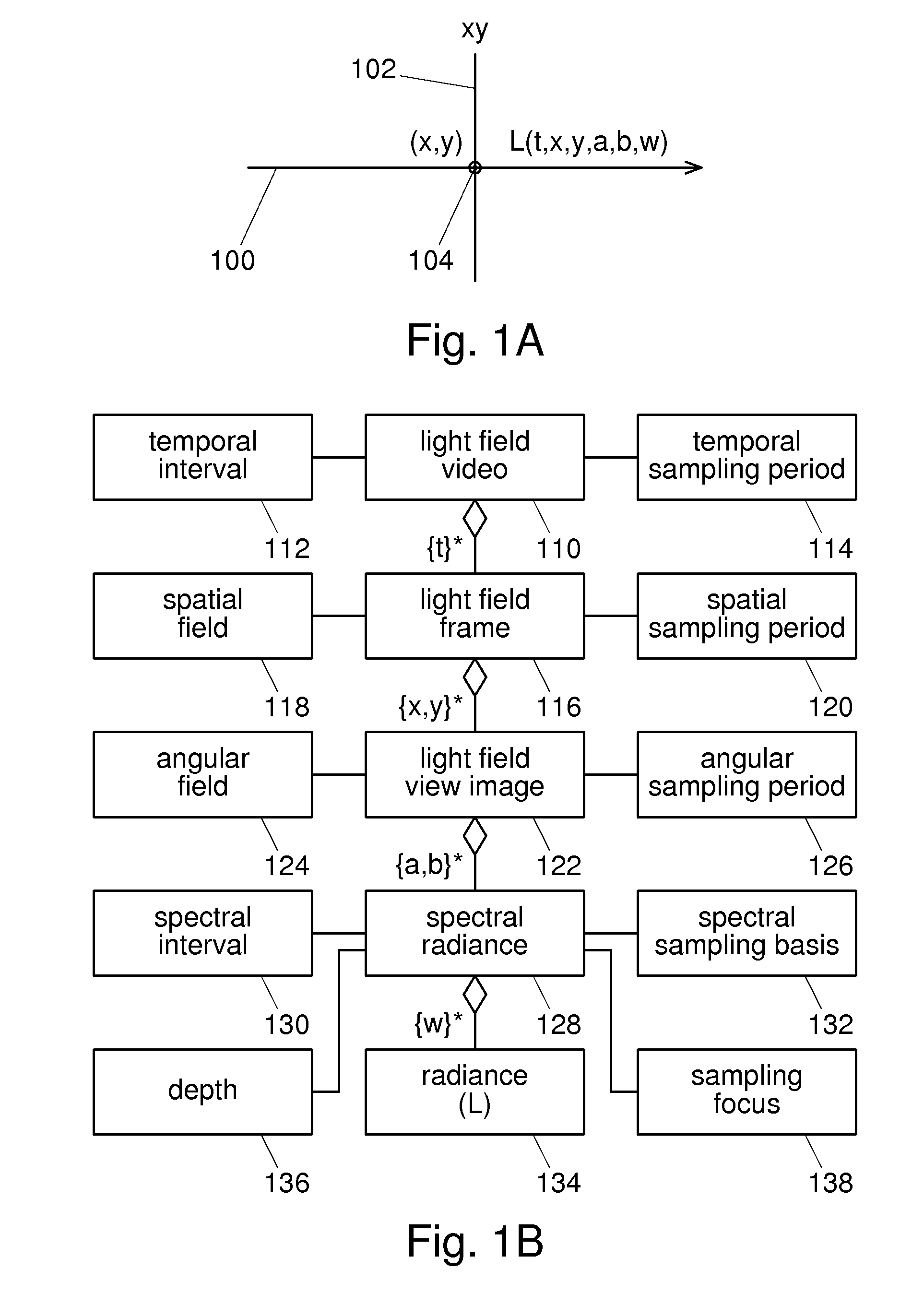
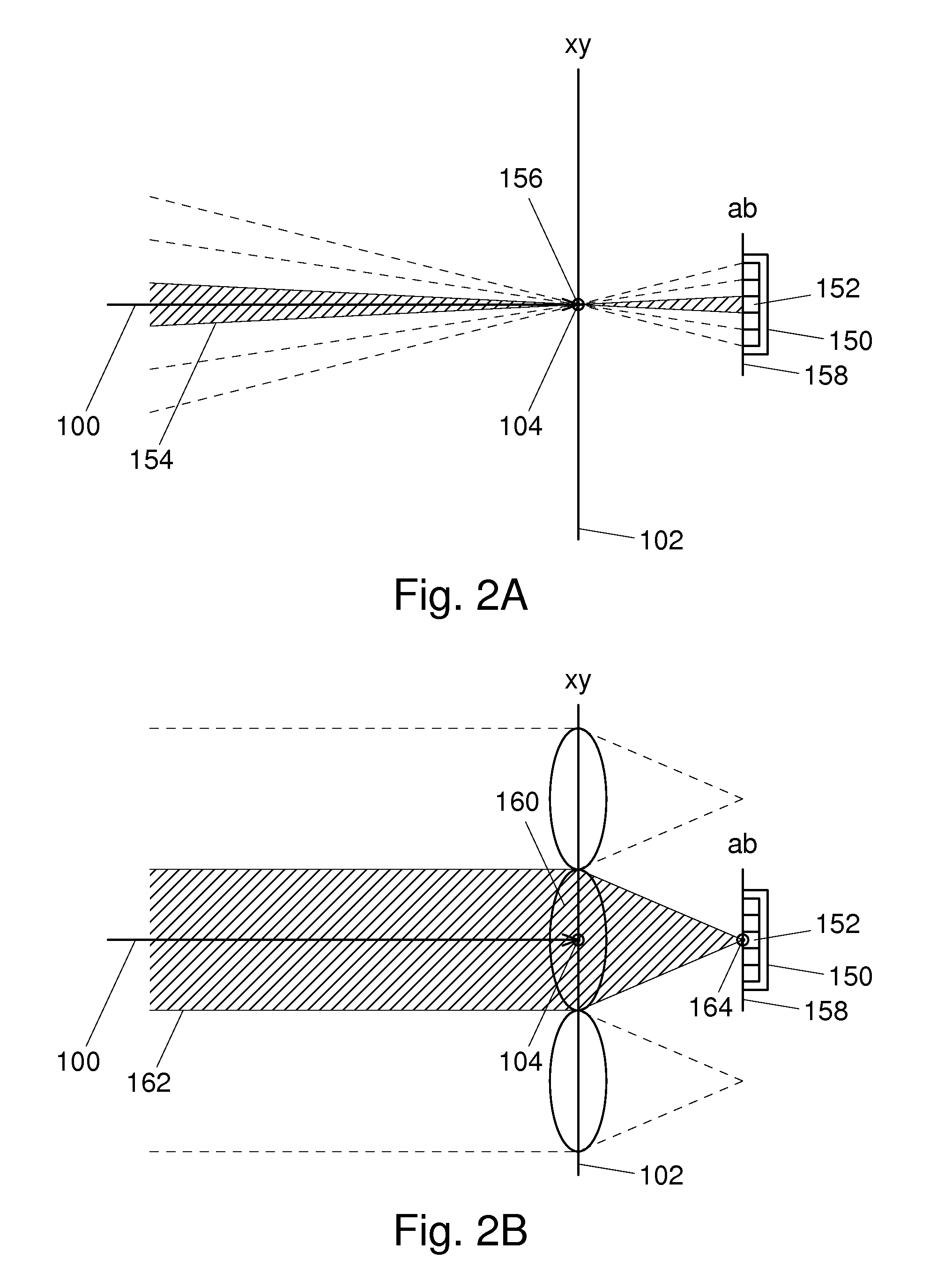
[0286]FIG. 1A shows a representative ray 100 of a continuous 6D light field, traversing the boundary 102 of the volume of interest at an intersection point104. The radiance (L) of the ray 100 is a function of time (t), boundary position (via coordinates x and y), ray direction (via angles a and b), and wavelength (w).

[0287]While the radiance of the ray is strictly only defined at the boundary, i.e. at the intersection point 104, additional knowledge of the transparency of the two volumes separated by the boundary can allow the ray's radiance to be extrapolated in either direction.

[0288]Radiance is a measure of radiant power per unit solid angle per unit area (measured in watts per steradian per square meter, W / sr / m^2). For an infinitesimal ray of a continuous light field, the radiance is defined for an infinitesimal solid angle and area.

[0289]For eventual display to a human, the radiance is usually sampled sparsely using either a triplet of basis function...


PUM


Abstract

The present invention provides a light field camera and display device (300) comprising an array of light field camera and display elements (310), each element (310) comprising: a scanner (504, 506) for scanning an input beam (600) and an output beam (500) across a two-dimensional angular field; an input focus modulator (612) for modulating the focus of the input beam (600) over time; a radiance sensor (604) for sensing the radiance of the input beam (600) over time; a radiance sampler (606) for sampling the radiance of the input beam (600) at discrete times; a beam generator (522) for generating the output beam (500); a radiance modulator (524) for modulating the radiance of the output beam (500) over time; and an output focus modulator (530) for modulating the focus of the output beam (500) over time.

Description

FIELD OF THE INVENTION[0001]The present invention relates to high-fidelity light field displays, cameras, and two-way displays.BACKGROUND OF THE INVENTION[0002]A 7D light field (or plenoptic function [Adelson91]) defines the spectral radiance of every ray passing through every point in a volume of space over time, and therefore contains every possible view within that volume. A 6D light field defines the spectral radiance of every ray passing through a given surface over time, i.e. it represents a slice through a 7D light field.[0003]Typically, only rays passing through the surface in one direction are of interest, e.g. rays emitted by a volume bounded by the surface. The 6D light field at the boundary can be used to extrapolate the 7D light field of the surrounding space, and this provides the basis for a light field display. The extrapolation is performed by rays emitted by the display as they propagate through space.[0004]Although an optical light field is continuous, for practic...

Claims


Application Information

Patent Timeline
Patent Type & Authority Patents(United States)
IPC IPC(8): G09G5/00G06T15/00
CPCG02F1/33G02F1/19G02B26/085H04N13/0468G02B27/0093G02B27/225G09G3/007G02F1/17G02B26/101G02F1/29G02B26/0833G09G2354/00G09G3/003G02F1/11H04N13/0484G02B26/08G02B26/10G02B27/2214G09G5/10G02F1/01G02B26/0875H04N13/00G09G3/02H04N13/0402H04N5/2256H04N5/23232H04N13/243H04N13/302H04N13/383G02B30/10G02B27/0075G02F1/294H04N23/957H04N23/61H04N23/67G06T19/006G02B30/27H04N23/54H04N23/56H04N23/951H04N25/745G09G2320/064G09G2360/141
Inventor LAPSTUN, PAUL
Owner VERGENT RES PTY LTD
Why Eureka
Try Eureka