Method and apparatus for attaching a supported addition to a finished building

a technology for adding structures and finished buildings, applied in mechanical equipment, building repairs, washing machines, etc., can solve the problems of breech in the integrity of finished buildings, require ongoing maintenance, etc., and achieve the effect of saving time, simple and effective, and maximally convenient us

Inactive Publication Date: 2014-06-24
JOHNSON JEFFREY K
View PDF18 Cites 19 Cited by
  • Summary
  • Abstract
  • Description
  • Claims
  • Application Information

AI Technical Summary

Benefits of technology

[0004]It is an object of this invention to disclose a simple and effective method of attaching an addition to the structural frame of an existing building. It is an object of this invention to disclose an apparatus and method of attachment which minimally breeches the existing structure's wall thereby eliminating the need for initial repair and ongoing maintenance. It is yet a further object of this invention to disclose a self sealing point of attachment to the existing building's structure for the structure of the addition. It is a final object of this invention to disclose a method and apparatus which is not only extremely effective but maximally convenient and time saving to use.
[0005]One aspect of this invention provides for a spacer for use within an enlarged hole drilled through the exterior side portion of a building's wall to expose the building's structural frame to provide a point of solid attachment for a supporting structural member of an addition screwed to frame of the finished building's frame comprising: a) a wall insert weather sealing cup portion having a peripheral sidewall, and a bottom side wall which seats on the structural frame of the building, said bottom sidewall having a central axial bolt opening therethrough; and, b) a structurally reinforced bend prevention bolt spacing sleeve portion mated to fit within the cup portion, said sleeve portion also having an central axial bolt opening therethrough. After an exterior side of the structural frame of the building is sheathed the sealing cup portion can be directly attached to the structural frame of the building through a hole drilled through a wall sheathing. When the sheathed wall is finished the cup portion can be sealed in the exterior wall finish thereby preventing moisture from penetrating through the wall at the enlarged hole; and when the addition, spaced from the finished wall is screwed to the existing building's frame, not only will a substantial bending moment on the screws be sustained by the structurally reinforced bend prevention bolt spacing sleeve portion, but additionally water running off the addition onto the finished wall will be prevented from penetrating into the wall by the wall insert weather sealing cup portion surrounding the structurally reinforced bend prevention bolt spacing sleeve portion and the screw therein.

Problems solved by technology

The problem with removing a portion of the exterior wall of the existing building is that it presents a breech in the integrity of the finished building.
Reliably sealing the opening is not only an initial concern, but all too often it requires ongoing maintenance.

Method used


Image

  • Method and apparatus for attaching a supported addition to a finished building
  • Method and apparatus for attaching a supported addition to a finished building
  • Method and apparatus for attaching a supported addition to a finished building

Examples


Embodiment Construction

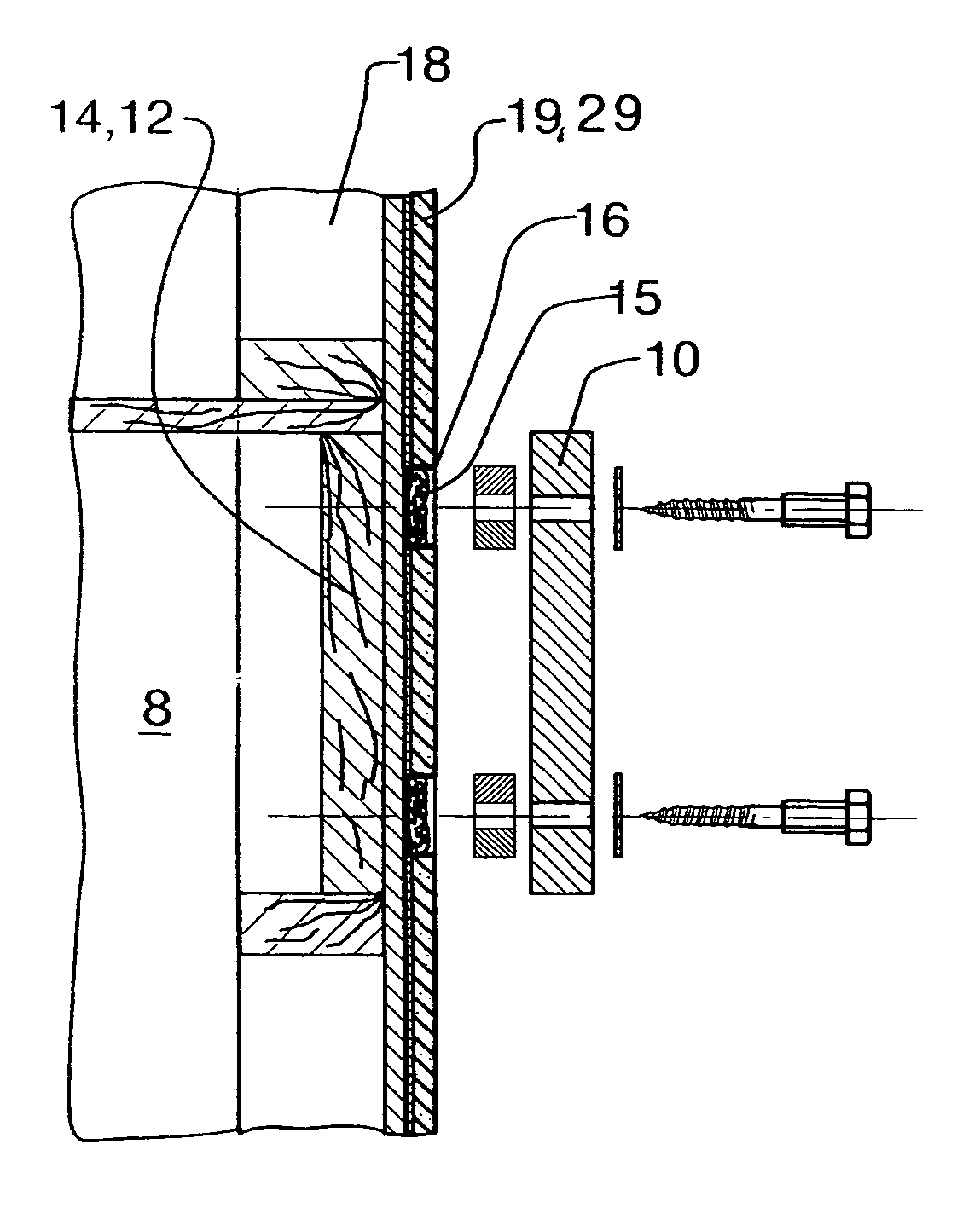
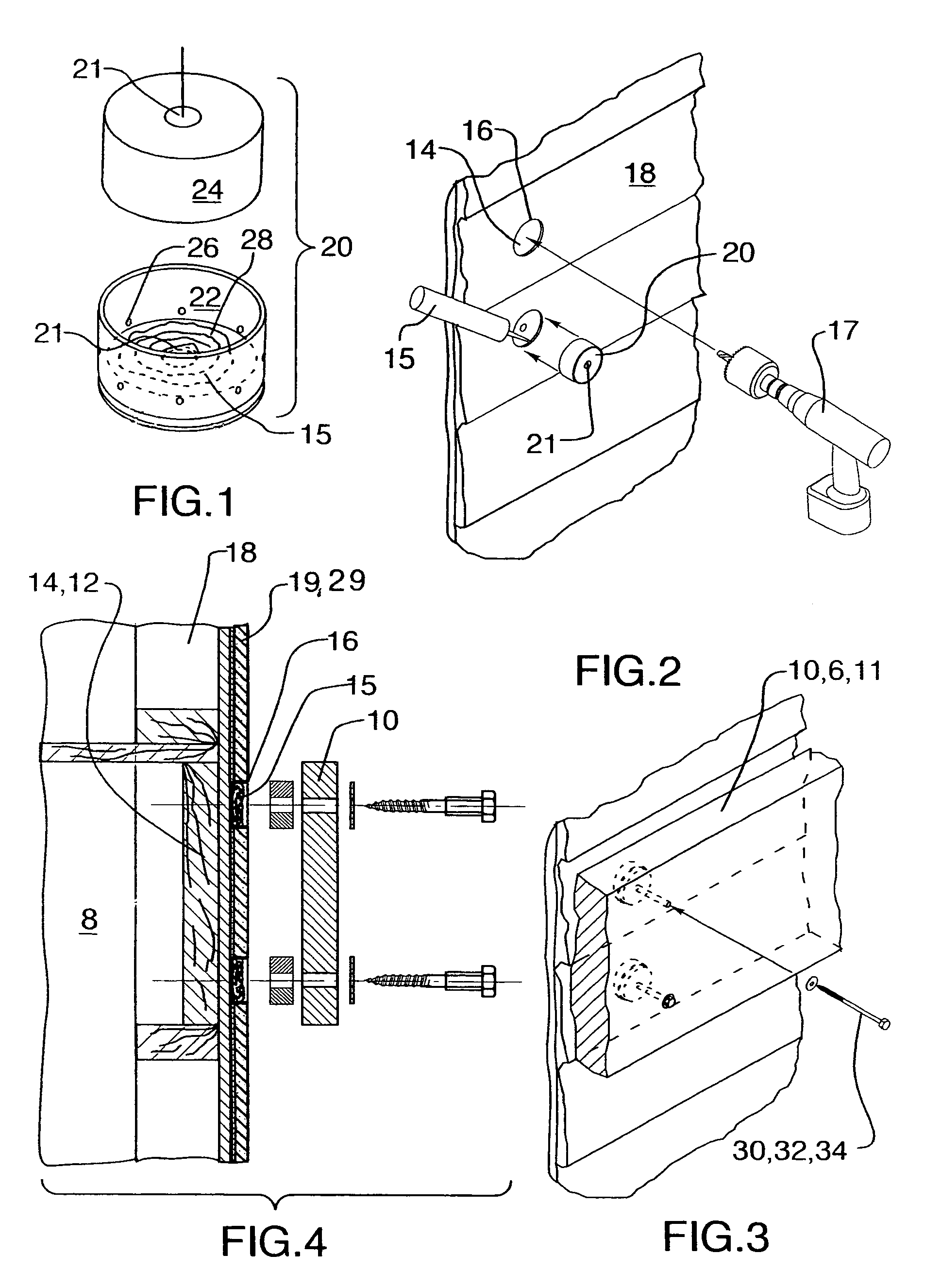
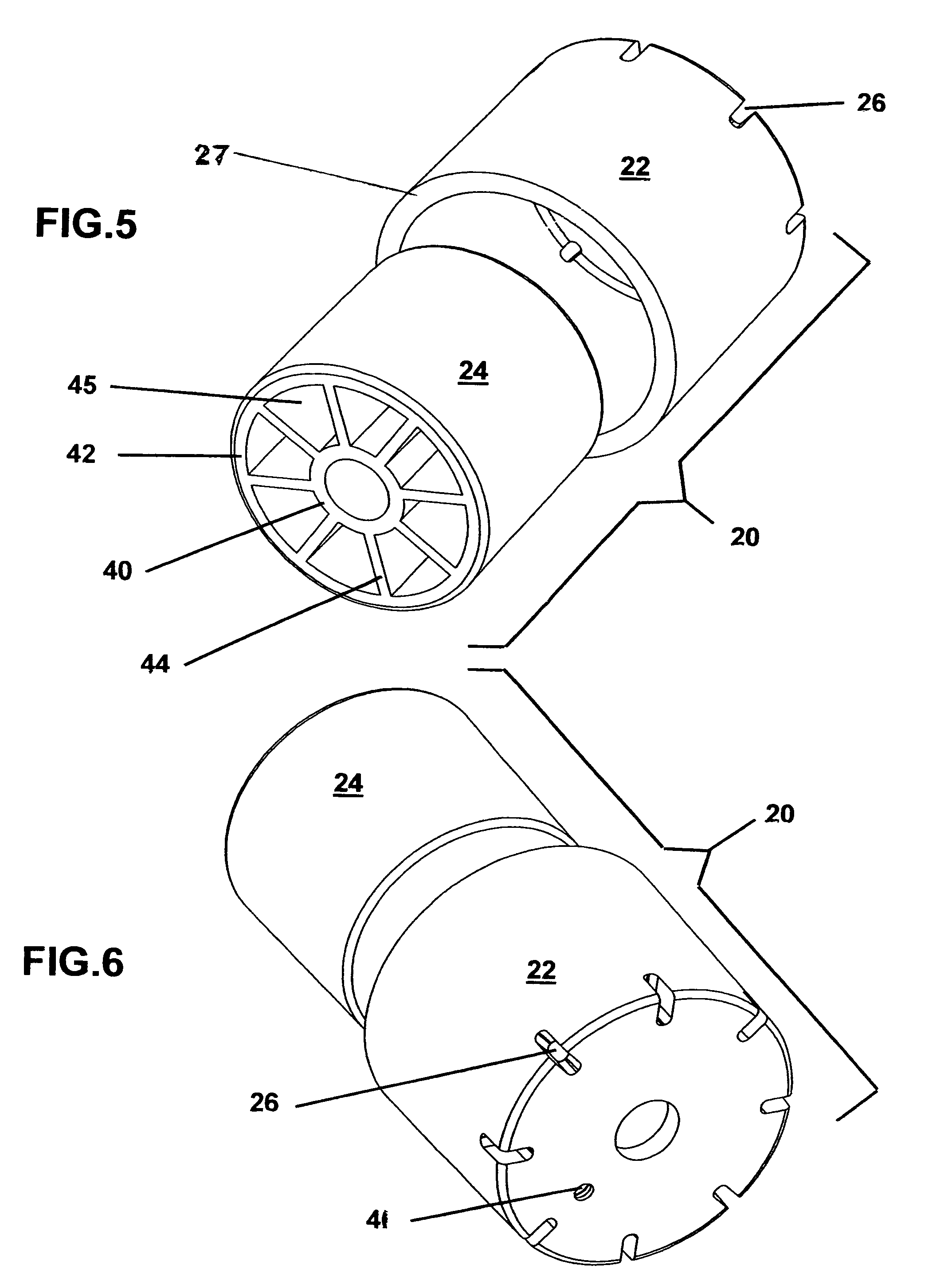
[0015]Turning now to the drawings and more particularly to FIG. 1 we have an enlarged exploded perspective view of a self sealing building spacer 20. FIG. 2 is a broken out perspective view of a finished building wall having spaced enlarged holes drilled therein. The enlarged holes 16 are drilled through an exterior portion of the building wall 18 to expose the building's supporting frame 14. Spacers 20 are inserted and closely received within the enlarged holes 16. FIG. 3 is the broken out perspective view of the exterior wall 18 shown in FIG. 1 further comprising a structural member 10 attached to the building's structural frame 14 thereunder. Lag bolts 32 positioned through the addition structural member 10, continuing through central axial opening 21 finally are threaded within the structural frame 14 beneath the exterior building wall 18. Most generally a spacer 20 for use within an enlarged hole 16 drilled 17 through the exterior side portion of a building's wall 18 to expose ...


PUM


Abstract

A spacer comprising: a) a wall insert weather sealing cup portion having a peripheral sidewall, and a bottom sidewall which seats on a structural frame of the building; and, b) a structurally reinforced bend prevention bolt spacing sleeve portion mated to fit within the cup portion, the sleeve portion having an central axial bolt opening therethrough. After an exterior side of the structural frame of the building is sheathed the sealing cup portion can be directly attached to the structural frame of the building through a hole drilled through a wall sheathing. When the sheathed wall is finished the cup portion can be sealed in the finish thereby preventing moisture from penetrating through the wall at the enlarged hole; and, when the addition is screwed to the existing building's frame, a substantial bending moment on the screws can be sustained by the structurally reinforced bend prevention bolt spacing sleeve portion.

Description

PRIOR APPLICATION[0001]This application is filed as a Continuation In Part of U.S. application Ser. No. 11 / 488,104 filed Jul. 18, 2006 now abandoned by Jeffery K. Johnson.FIELD OF THE INVENTION[0002]This invention relates to solidly attaching an added structure such as a deck, a deck cover, or a shed to the structural frame of an existing building. More particularly this invention relates to using a spacer which attaches to the structural frame on one of its ends, sealably spaces beyond and attaches to the siding of the finished building on its central portion, to thereby provide a solid point of attachment for a new structure on its other outer end portion.BACKGROUND OF THE INVENTION[0003]When an added structure such as a deck, a deck cover, or a shed has an attached side which is carried by a finished building it is necessary to solidly attach the added structure to the frame of the existing building. To provide a solid point of attachment it is necessary to remove the finished ex...

Claims


Application Information

Patent Timeline
Patent Type & Authority Patents(United States)
IPC IPC(8): E04G23/00E04F19/00
CPCE04B1/003F16B43/001E02D31/02
Inventor JOHNSON, JEFFREY, K.
Owner JOHNSON JEFFREY K
Why Eureka
Try Eureka