Devices and methods for non-invasive optical physiological measurements

a physiological measurement and optical technology, applied in the field of non-invasive optical physiological measurement devices, can solve the problems of unreliable methods and noisy baseline of ac signal components, and achieve the effects of high signal-to-noise ratio, accurate measurement, and high signal-to-noise ratio

Active Publication Date: 2014-06-24
NITTO DENKO CORP
View PDF9 Cites 30 Cited by
  • Summary
  • Abstract
  • Description
  • Claims
  • Application Information

AI Technical Summary

Benefits of technology

[0010]Described herein is an optical measurement device for obtaining non-invasive physiological measurements from a portion of living tissue and method of using the same, which more particularly includes a pressure detection assembly configured to detect and display an amount of pressure applied by a body part of a user to the device during the optical measurement. When a user applies an appropriate amount of pressure to the optical measurement device, the resulting signal-to-noise ratio of the detected optical measurement signal, such as a photoplethysmography signal, can be increased, and a more accurate measurement can be obtained from the user. An optimum pressure can be determined in real-time by analyzing the detected optical measurement signal and correlating a high signal-to-noise ratio portion of the signal with a corresponding applied pressure. The user is then provided real-time feedback indicating whether the amount of pressure being applied by the user should be increased, decreased or maintained at the same level in order to continually obtain the highest quality signal. The optical measurement device can therefore provide an optimal pressure determination customized for each individual user, thereby obtaining a resulting optimal measurement signal for each user.

Problems solved by technology

However, these methods are unreliable when the detected signal is less than ideal.
Particular problems may be encountered when the baseline of the AC signal component becomes noisy or complex, as can occur even with mild movement artifacts.

Method used


Image

  • Devices and methods for non-invasive optical physiological measurements
  • Devices and methods for non-invasive optical physiological measurements
  • Devices and methods for non-invasive optical physiological measurements

Examples


Embodiment Construction

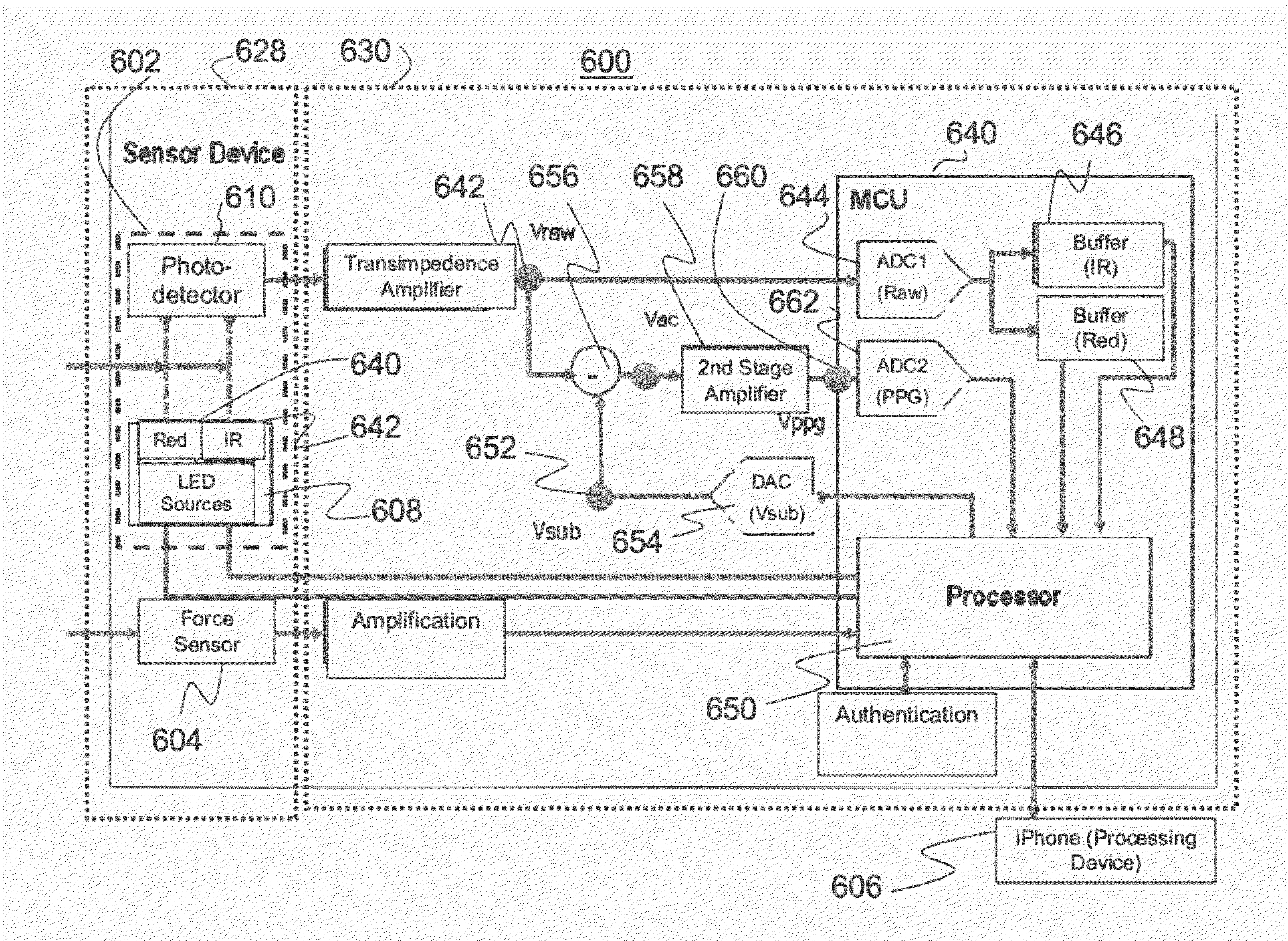
[0060]An optical measurement device for obtaining non-invasive physiological measurements and method of using the same is described more fully herein, including the pressure detection assembly configured to detect and display an amount of pressure applied by a body part of a user to the device during the optical measurement. When the user applies an appropriate amount of pressure to the optical measurement device, the resulting signal-to-noise ratio of the detected optical measurement signal can be increased, and a more accurate measurement signal can be obtained from the user. An optimal pressure can be determined in real-time by analyzing the detected optical measurement signal and correlating a high signal-to-noise ratio portion of the signal with a corresponding applied pressure. The user is then provided real-time feedback indicating whether the amount of pressure being applied by the user should be increased, decreased or maintained at the same level. The optical measurement d...


PUM


Abstract

An optical measurement device and method of use provides non-invasive physiological measurements from a predetermined location on a body part of a user. The optical measurement device provides an illumination and detection assembly configured to generate and detect light of a predetermined wavelength range in the form of a photoplethysmography (PPG) signal, as well as a pressure detection assembly configured to detect an amount of pressure applied to the measurement device by the user being measured. A feedback unit, such as a portable display device, provides the user real-time feedback of the detected PPG signal and level of applied pressure so that the user may adjust the amount of applied pressure to improve the quality of the detected PPG signal.

Description

BACKGROUND[0001]1. Field of the Invention[0002]This invention relates to devices and methods for non-invasive optical physiological measurements, including the detection of a photoplethysmography (PPG) signal from a user, and more particularly to a pressure detection assembly of an optical measurement device which detects an amount of pressure applied by the user to the device, and a feedback unit which aids the user in determining an optimal PPG signal.[0003]2. Description of the Related Art[0004]Optical monitoring of physiological characteristics utilizes the detection of light transmitted through a location of a user being measured. Photoplethysmography (PPG) is an optical measurement technique used to detect blood volume changes in the microvascular bed of living tissue, typically by detecting light transmitted through the ear lobe or fingertip. As arterial pulsations enter the capillary bed, changes in the volume of the blood vessels or characteristics of the blood itself modif...

Claims


Application Information

Patent Timeline
Patent Type & Authority Patents(United States)
IPC IPC(8): A61B5/1455
CPCG01N21/3151A61B5/6898G01N2021/3144A61B2562/0247A61B5/1455A61B5/0059A61B5/7435A61B5/14551A61B5/02416A61B5/0295A61B5/6843A61B5/7203A61B2562/227F04C2270/041
Inventor THAVEEPRUNGSRIPORN, VISITKASSIM, MD IRWAN BIN MDNAING, NYAN MYOSAMSUDIN, MOHAMAD SULHEDE BIN
Owner NITTO DENKO CORP
Why Eureka
Try Eureka