Reuseable bottle cap having identification means
a bottle cap and identification technology, applied in the field of reusable bottle caps, can solve the problems of confusion as to the ownership of various drinks, and achieve the effect of improving the grasping of bottle caps
- Summary
- Abstract
- Description
- Claims
- Application Information
AI Technical Summary
Benefits of technology
Problems solved by technology
Method used
Image
Examples
embodiment 115
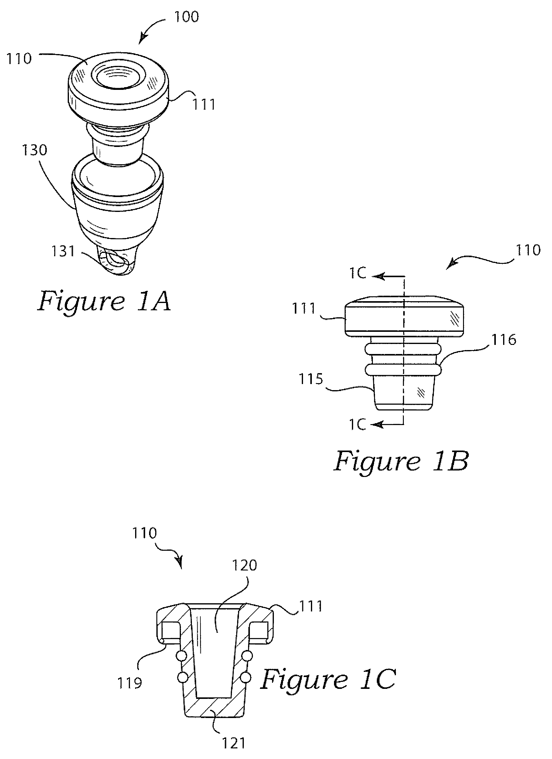
[0049]With regard to FIG. 1B and FIG. 1C, profile and sectional views of the first preferred bottle cap 110 are illustrated respectively. The cap 110 generally includes a stem portion 115 and a flanged ring portion 111 about an upper end of the stem portion 115. The stem 115 is configured to mate with an inner rim of a beverage (especially water) bottle opening, as shown in FIG. 5 and FIG. 6A through FIG. 6E. The stem portion 115 is additionally characterized in that it is hollow 120 through its length except that its bottom end is closed 121 (FIG. 1C). In this and in other embodiments, the stem further has a slight taper 218 (FIG. 2G) from top to bottom 121 to fit the inner rim of the mouth of beverage (especially water) bottles of varying inner diameters (FIGS. 5 and 6A through 6E). This particular stem embodiment 115 comprises two grooves machined around a circumference thereof; the grooves are additionally configured to receive two O-rings 116 wherein the O-rings assist in formi...
embodiment 310
[0055]FIG. 3A illustrates a perspective view of a third preferred bottle cap 310 embodiment of the present invention; FIG. 3B is a profile view of the third preferred embodiment 310; and FIG. 3C illustrates a cross-sectional view taken along sectional line 3C-3C. In this embodiment, the flanged ring portion 311 has an outside surface that extends outwardly and downward smoothly and continuously to form a rounded ring from lateral side to a top surface. Stated differently, the flanged ring portion 311 has a surface having a slope 312, the slope is continuously increasing and negative from a top to a lateral side without a step change in slope 312. Further, the flanged ring portion 311 is configured to fit around mouths of bottles of varying outer diameter. Additionally, the stein 315 is hollow 320 throughout its vertical axis through which a user may dispense of the contents or so that a straw would be permitted to fit through the stem 315.
[0056]FIG. 4 illustrates yet another reusabl...
embodiment 215
[0059]Now turning to FIG. 7A through FIG. 7E, another preferred embodiment of the present invention is illustrated and generally comprises reusable bottle cap 710 with a cover 730 thereto. FIG. 7A more specifically illustrates an identification marker 723 coupled to a flanged ring portion 711. Close inspection of FIG. 7A and FIG. 7B revels that the stem portion 715 comprises different structure than in previous embodiment. More particularly, the stern 715 has a cylindrical base 717 and therefore the surface between adjacent peaks 716 is substantially flat. The peaks 716 themselves are additionally different than previous embodiment in that they protrude outward with a slight convex surface; whereas the previous embodiment 215 comprises a concave surface 217 to a peak 216 also comprising a point 216, 716. Additionally, since the peaks 716 comprise a surface that is slightly convex, then also the peaks 716 are not flat or thin like a wafer.
PUM
| Property | Measurement | Unit |
|---|---|---|
| length | aaaaa | aaaaa |
| area | aaaaa | aaaaa |
| diameter | aaaaa | aaaaa |
Abstract
Description
Claims
Application Information
 - R&D
- Intellectual Property
- Life Sciences
- Materials
- Tech Scout
- Unparalleled Data Quality
- Higher Quality Content
- 60% Fewer Hallucinations
Browse by: Latest US Patents, China's latest patents, Technical Efficacy Thesaurus, Application Domain, Technology Topic, Popular Technical Reports.
© 2025 PatSnap. All rights reserved.Legal|Privacy policy|Modern Slavery Act Transparency Statement|Sitemap|About US| Contact US: help@patsnap.com


