
Geoposition determination by starlight refraction measurement

a technology of starlight refraction and position determination, applied in navigation instruments, instruments, image enhancement, etc., can solve the problems of unavoidable subject matter of method of position determination, high accuracy on a moving platform, and sensitive to knowledg

Active Publication Date: 2014-07-01
LOCKHEED MARTIN CORP
View PDF10 Cites 17 Cited by
  • Summary
  • Abstract
  • Description
  • Claims
  • Application Information

AI Technical Summary

Benefits of technology

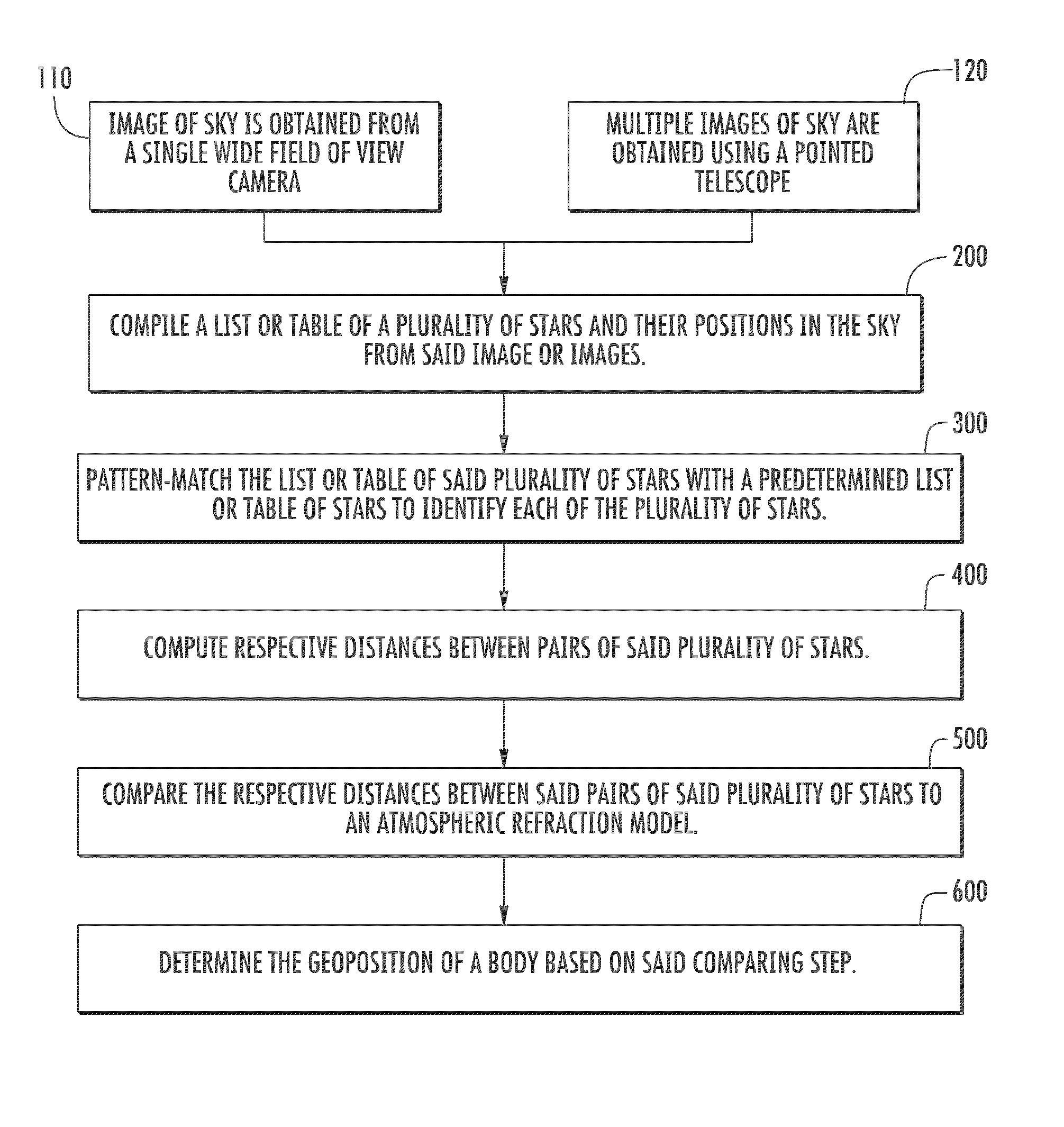
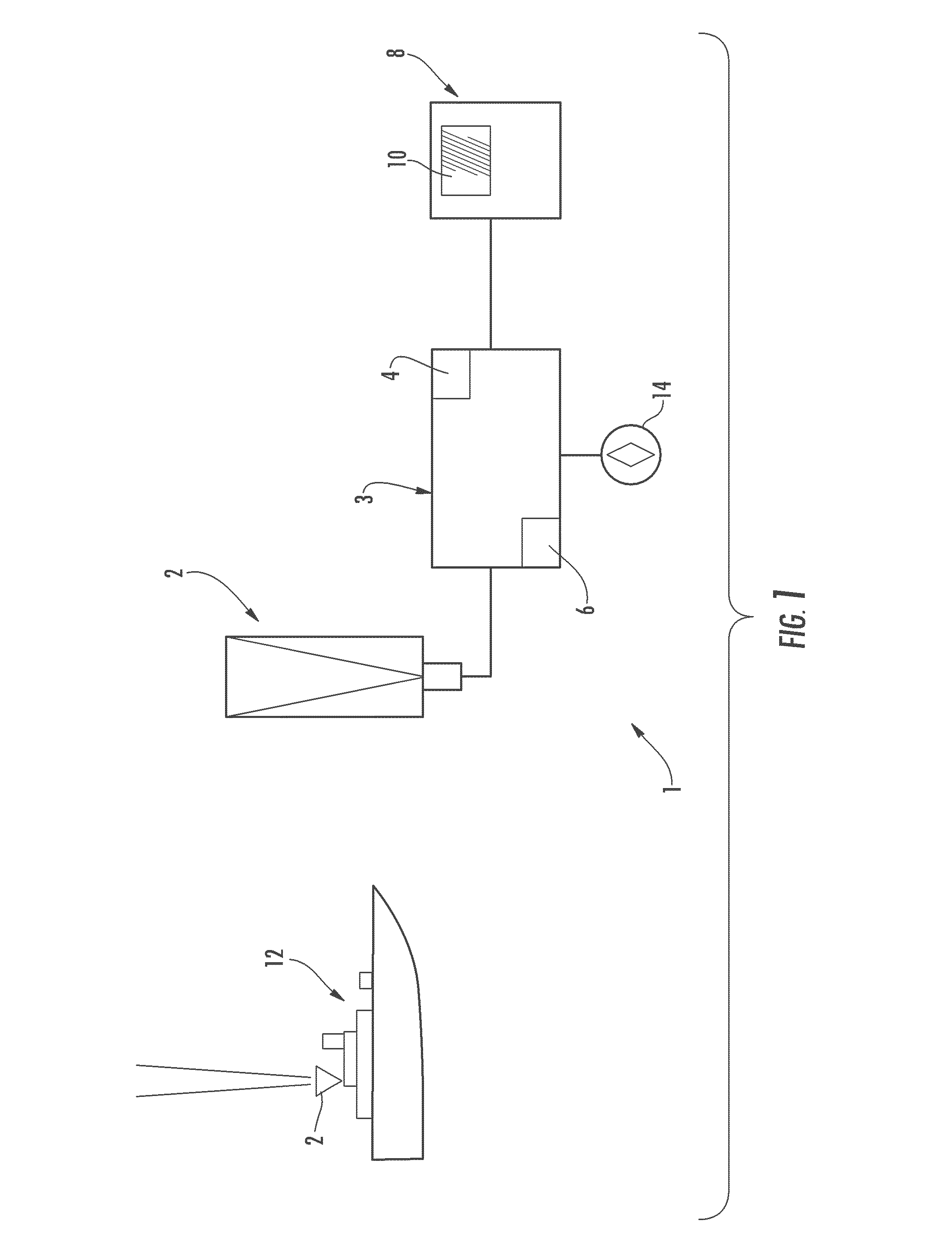
This patent describes a method and system for determining the geoposition of a moving platform without using GPS. The method involves capturing images of the sky and compiling a list of stars and their positions. These stars are then matched with a pre-determined list to identify each star. The relative distances between pairs of stars are compared to an atmospheric refraction model to determine the geoposition of the platform. The patent has applications in both military and commercial settings. The system includes a camera, sensor, and processor for performing the method.

Problems solved by technology

This method of position determination is unavoidably subject to drift errors which grow with time, making it useful for accurately determining position only over relatively short periods of time.
This method requires either visual measurement of the horizon or inertial measurement of the local gravity vector as a benchmark for all star observations and is therefore highly inaccurate on a moving platform.
This method, however, is sensitive to knowledge of the absolute knowledge of the position of the satellites.

Method used


Image

  • Geoposition determination by starlight refraction measurement
  • Geoposition determination by starlight refraction measurement
  • Geoposition determination by starlight refraction measurement

Examples


second embodiment

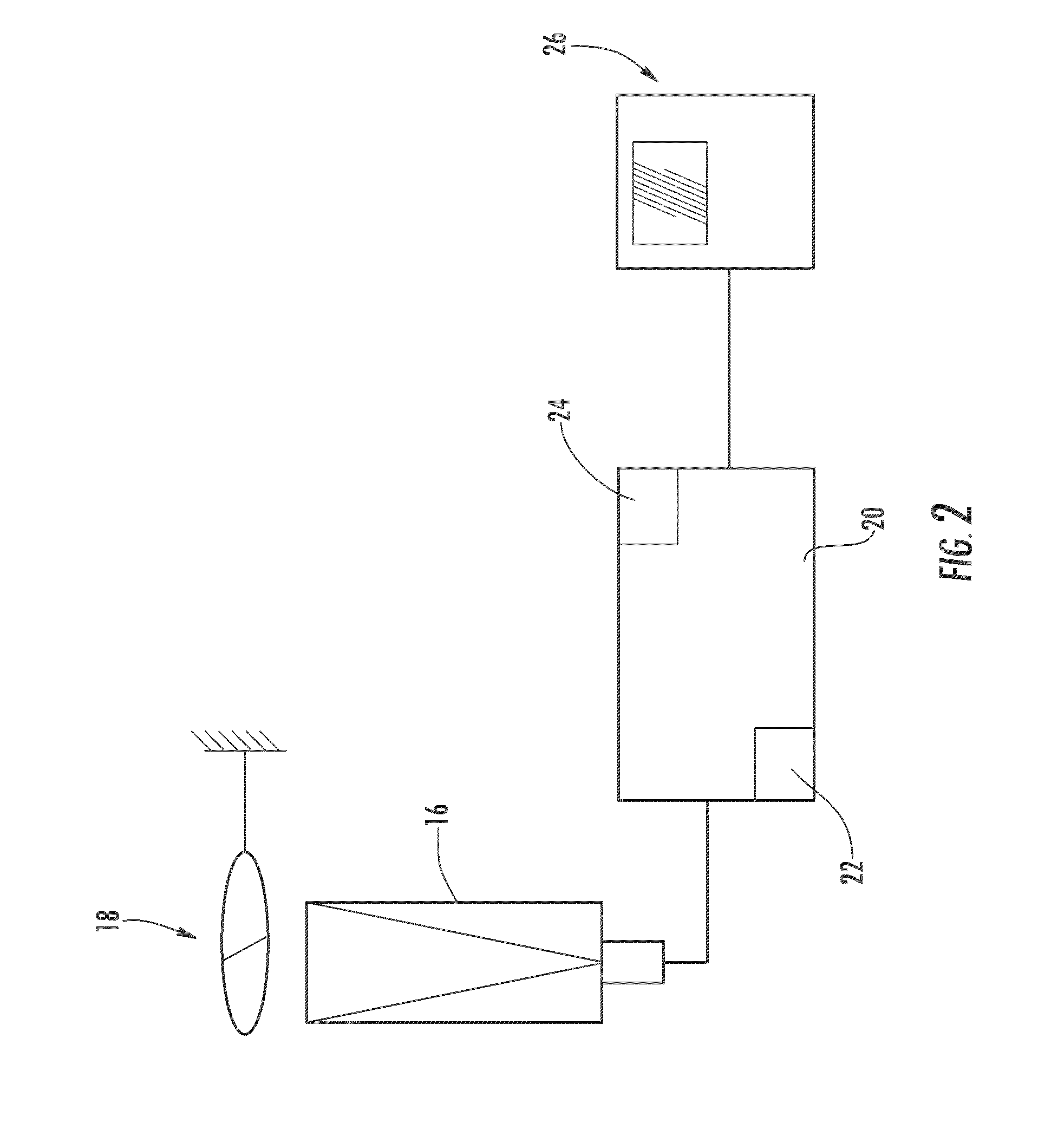
[0026]As in the first embodiment, the second embodiment uses either a single image of the sky taken with a sensor 16 such as a wide-field-of-view camera, or uses multiple images of single stars taken with a sensor such as a pointed telescope. Again, a gyroscope 14 can be used to track, and correct for, rotation of the platform between star sightings. In either case, a single table of all stars in the image or images is compiled and pattern-matched to identify each star in the image or images.

[0027]In the second embodiment, two images of each star (or the entire sky) are then taken simultaneously, or nearly simultaneously, using a sensor 16 or sensors which can detect two different frequency bands. In one embodiment, the first frequency band is the visible frequency band, and the second frequency band is the infrared frequency band. Because the atmosphere refracts each frequency of light by a different amount, the displacement between the two frequencies can be measured for each star...


PUM


Abstract

A system and method are disclosed for determining geoposition of an observer. The system includes a sensor such as a wide field of view camera or telescope that can capture an image of the sky. The image of the sky is used to compile a table or list of the stars in the sky along with their positions. This table or list is pattern-matched with a predetermined list or table of stars to identify each star. In one embodiment, the distances between all stars in the image are computed and compared to star images from an atmospheric refraction model. A comparison of the measured table or list and the refraction model, using an optimization algorithm, is performed to determine the geoposition of the observer. In an alternative embodiment, a sensor capable of measuring two different frequency bands obtains two images of each star in the sky simultaneously. A difference in displacement is determined between the two frequencies for each imaged star; and a magnitude and direction of the difference in displacement is used to determine the geoposition of a body.

Description

GOVERNMENT RIGHTS[0001]This invention was made with Government Support under Contract No. N00024-03-C-6110 awarded by the Department of the Navy. The Government has certain rights in this invention.FIELD OF THE DISCLOSURE[0002]The invention relates to geopositioning systems in general, and more particularly to a system for determining geoposition of a body using one or more starlight images in combination with atmospheric refraction models.BACKGROUND OF THE DISCLOSURE[0003]Position of a moving platform such as a ship at sea or a moving land vehicle is generally determined using a Global Positioning System (GPS). Without GPS, dead reckoning is often used in which measurements of angular rotation rates and translational accelerations (using gyroscopes and accelerometers) are integrated to calculate position. This method of position determination is unavoidably subject to drift errors which grow with time, making it useful for accurately determining position only over relatively short ...

Claims


Application Information

Patent Timeline
IPC IPC(8): H04N11/18
CPCH04N11/18G01S3/7867G01C21/025G06T7/74G06T2207/30212
Inventor ROSENWINKEL, ALAN, M.
Owner LOCKHEED MARTIN CORP
Learn More