Target image registration and fusion

Inactive Publication Date: 2014-07-01
GOVERNMENT OF THE UNITED STATES AS REPRESENTED BY THE SEC OF THE AIR FORCE
View PDF23 Cites 5 Cited by
  • Summary
  • Abstract
  • Description
  • Claims
  • Application Information

AI Technical Summary

Benefits of technology

[0014]Second, an optimality procedure to employ only those target images that add value is accomplished by a statistical approach based on maximum likelihood values. Specifically, selection of appropriate target images can be converted into a simple identification problem of discerning signal versus noise and employing likelihood functions to select target images that, in an analogous sense, include a signal over and above the “noise” of a reference image. Eliminatio

Problems solved by technology

A particular problem is computation cost, particularly computational speed.
Complicating this process is that an original reference image may be compromised by

Method used


Image

  • Target image registration and fusion
  • Target image registration and fusion
  • Target image registration and fusion

Examples


example calculation

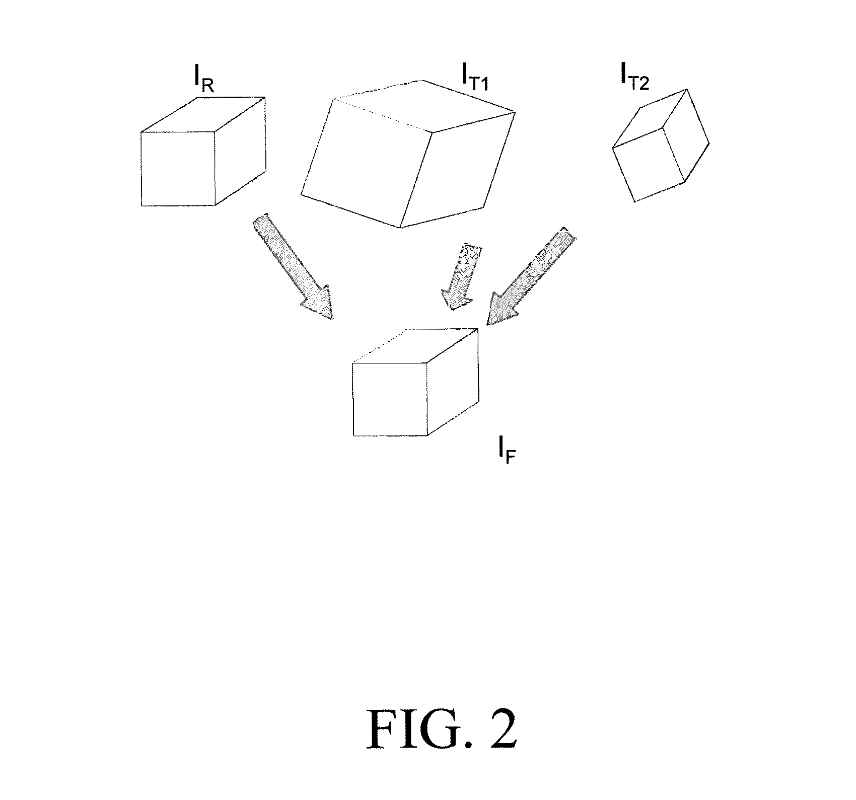
[0084]To illustrate the “skeletonization” effect of the first solution component, an example is worked consisting of an image involving a geometric figure as the reference image IR. As before, two target images IT1 and IT2 will be combined with IR to produce a fused image IF. The overall goal is that fused image IF combines important details about the target images and enhances the reference image in terms of its information content. In this example, the two target images are deliberately selected to provide additional information and do not require weighing of the second solution component. The images in this example were also constructed on a computer using MATLAB® (with its image processing toolbox) to apply equations (2) through (14) to produce the same result as shown in FIGS. 5-8.

[0085]The reference image IR in this example is a simple right triangle 50 on a white background as shown in FIG. 5.

[0086]The line widths of triangle 50 are one pixel wide. The dimensions of triangle ...


PUM


Abstract

A new optical imaging process for how to best fuse information from multiple target images into a single target image is described. The process has two primary components. First, rotating, translating and scaling each target image to register or calibrate them against a reference image and, second, determining weighing factors for each thus registered target image to select those images which add value to a final target image. The first component determines optimal rotational and translation matrices by a least squares measure using singular value decomposition. The second component determines weighing factors using correlations and statistical signal analysis techniques.

Description

CROSS REFERENCE TO RELATED PATENT APPLICATIONS[0001]This application claims priority under 35 U.S.C. §119(e) from U.S. provisional application 61 / 360,053, filed Jun. 30, 2010 and titled “Image Registration and Fusion Optimization.” The invention description contained in that provisional application is incorporated by reference into this description.[0002]This application is related to U.S. patent application Ser. No. 12 / 471,543, filed May 26, 2009, titled “Dynamic Image Registration” and identified as Air Force invention number AFD 1001, but does not claim priority under 35 U.S.C. §120 to its filing date. The invention description in that application is incorporated by reference into this description.[0003]This application is also related to U.S. patent application Ser. No. 11 / 805,262, filed May 18, 2007, titled “Visual Object Identification by Computational Majority” and identified as Air Force invention number AFD 935, but does not claim priority under 35 U.S.C. §120 to its filing...

Claims


Application Information

Patent Timeline
IPC IPC(8): G06K9/32
CPCG06K9/32G06K9/6247G06K9/6289G06V10/7715G06V10/242G06T7/33G06F18/251G06F18/2135
Inventor REPPERGER, DANIEL W.ROBERTS, RODNEY G.PINKUS, ALAN R.SORKIN, ROBERT D.
Owner GOVERNMENT OF THE UNITED STATES AS REPRESENTED BY THE SEC OF THE AIR FORCE
Why Eureka
Try Eureka