Ignition current tester

Inactive Publication Date: 2011-06-14
MONINGER JOHN A
View PDF13 Cites 3 Cited by
  • Summary
  • Abstract
  • Description
  • Claims
  • Application Information

AI Technical Summary

Benefits of technology

[0014]Yet still another object of the present invention is to allow an engine to run with the apparatus in place such that a user can observe whether the ignition system is functioning properly under operational conditions, allowing the user to identify problems such as intermittent i

Problems solved by technology

Since the spark is provided in the interior of the combustion cylinder, a mechanic must rely on other indications of a proper spark which may not be highly reliable.
The verification of proper spark firing is a time consuming and difficult process which is nonetheless critical in the assessment of engine repair.
Such methods are expensive due to the time and labor involved in the removal and replacement processes.
While these devices fulfill their respective, particular objectives, each of

Method used


Image

  • Ignition current tester
  • Ignition current tester
  • Ignition current tester

Examples


Embodiment Construction

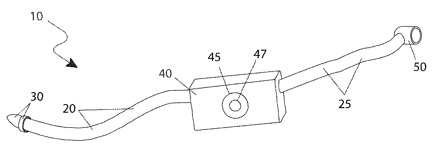
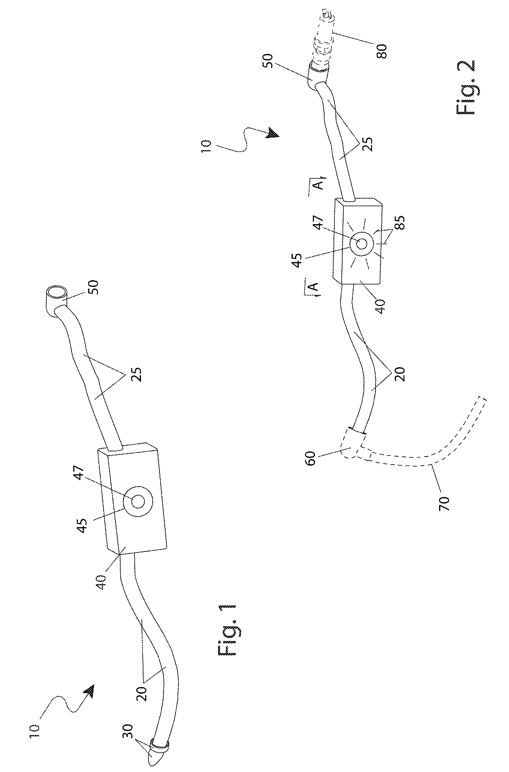
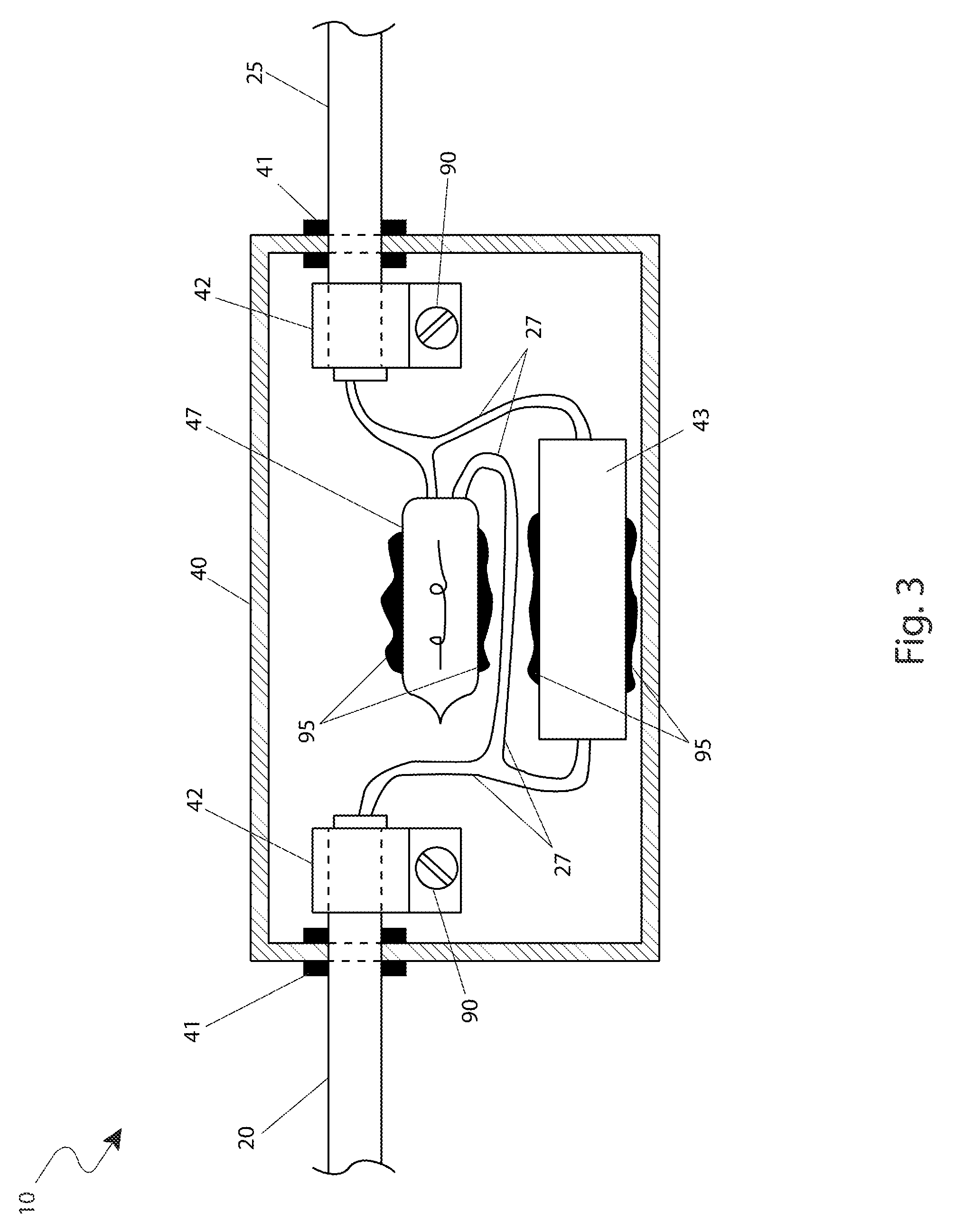
[0042]The best mode for carrying out the invention is presented in terms of its preferred embodiment, herein depicted within FIGS. 1 through 4. However, the invention is not limited to the described embodiment and a person skilled in the art will appreciate that many other embodiments of the invention are possible without deviating from the basic concept of the invention, and that any such work around will also fall under scope of this invention. It is envisioned that other styles and configurations of the present invention can be easily incorporated into the teachings of the present invention, and only one particular configuration shall be shown and described for purposes of clarity and disclosure and not by way of limitation of scope.

[0043]The terms “a” and “an” herein do not denote a limitation of quantity, but rather denote the presence of at least one of the referenced items.

[0044]The present invention describes an ignition current tester (herein described as the “apparatus”) 1...


PUM


Abstract

An apparatus to aid in the testing of engine ignition systems is herein disclosed. The apparatus is connected in a series wiring path between a spark plug wire and a spark plug of an internal combustion-type engine. The apparatus comprises a housing containing a resistor and a lamp which provide illuminated indication of a current flowing through the apparatus. The apparatus allows a user to quickly determine if an ignition circuit of an engine is operating properly.

Description

RELATED APPLICATIONS[0001]The present invention was first described in and claims the benefit of U.S. Provisional Patent No. 61 / 214,392 filed Apr. 24, 2009, the entire disclosures of which are incorporated herein by reference.FIELD OF THE INVENTION[0002]The present invention relates generally to automobile ignition systems, and in particular, to a device adapted for quickly and accurately assessing the state of a spark plug ignition portion of an automobile ignition system.BACKGROUND OF THE INVENTION[0003]One (1) particular type of work found around motor vehicles, small engine repair shops, farms, and the like is that of engine repair. One (1) critical factor that must be verified at an early stage of repair diagnosis is that of a proper spark being supplied by the ignition system. Since the spark is provided in the interior of the combustion cylinder, a mechanic must rely on other indications of a proper spark which may not be highly reliable.[0004]The verification of proper spark...

Claims


Application Information

Patent Timeline
IPC IPC(8): F02P17/00
CPCH01T13/60F02P17/12
Inventor MONINGER, JOHN A.
Owner MONINGER JOHN A
Why Eureka
Try Eureka