Electric vehicle supply equipment testing apparatus
a technology for electric vehicles and testing equipment, which is applied in the direction of power supply testing, electric devices, instruments, etc., can solve the problems of inability to check the function of electric vehicles, lack of a mechanism for electric vehicles, and relatively high cost of electric vehicles
- Summary
- Abstract
- Description
- Claims
- Application Information
AI Technical Summary
Benefits of technology
Problems solved by technology
Method used
Image
Examples
example 1
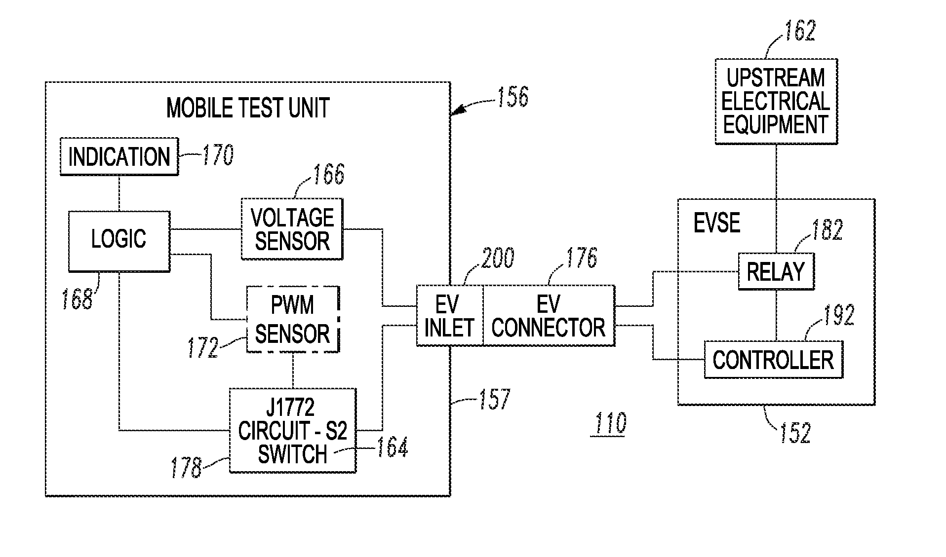
[0041]One example of the logic 168 of FIG. 4 is as follows.
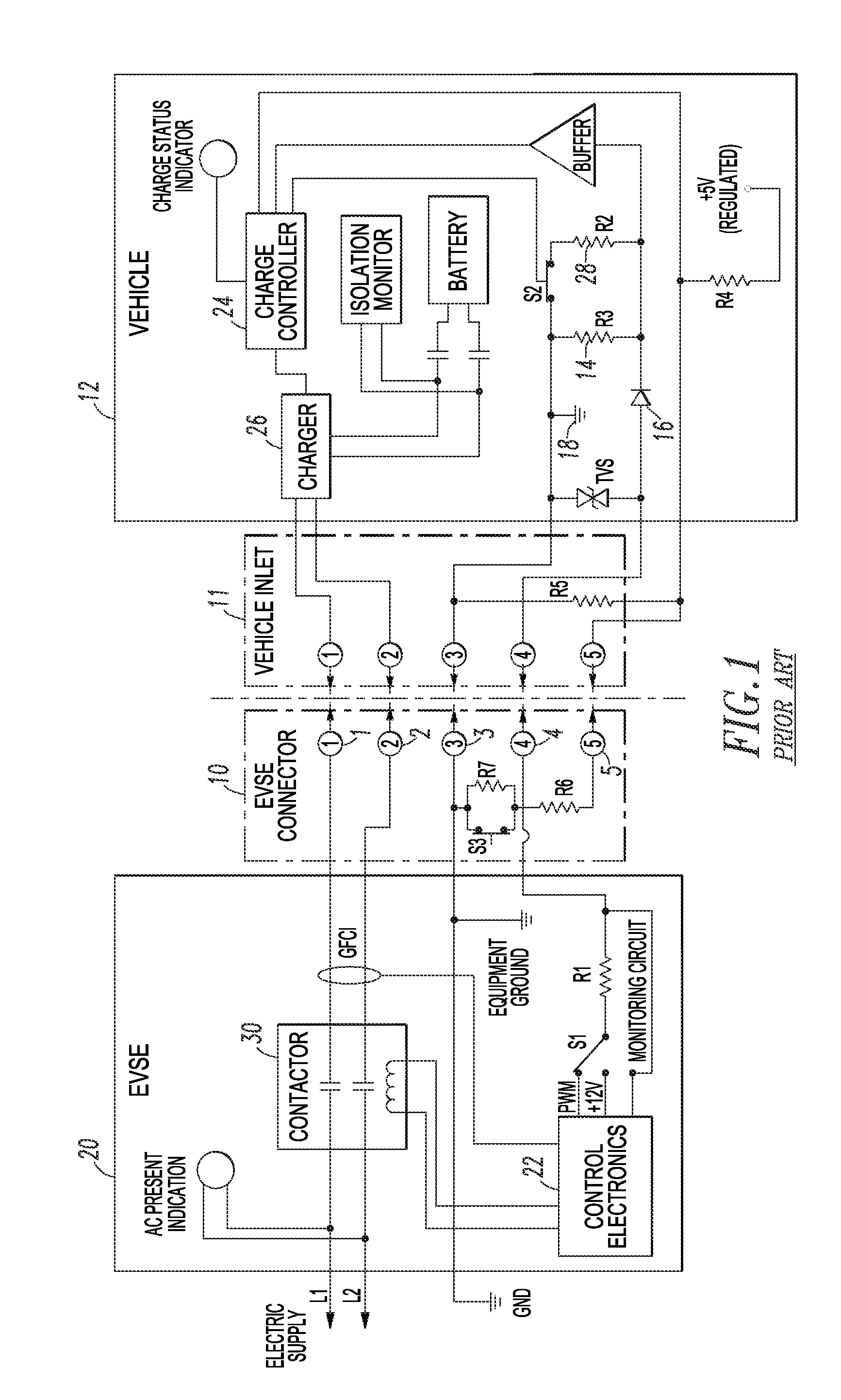
[0042]If the EV inlet voltage is >0 at voltage sensor 166, if the EVSE state is not ReadyToCharge (i.e., the pilot pin 4 of FIG. 1 is 9 Vdc), and if the EV inlet voltage is 120 Vac and the PWM current indication is 172, then indicate at 170 that INTERLOCK_NOT_IMPLEMENTED_BUT_OK.
[0043]Otherwise, indicate that: INTERLOCK_FAILED_AND_REQUIRED, and recommend fixes or causes: INTERLOCK_FAILED_AND_REQUIRED.
[0044]If the EVSE state is ReadyToCharge (i.e., the pilot pin 4 of FIG. 1 is 6 Vdc), and if the EV inlet voltage is 208 Vac or 240 Vac, then indicate that: INTERLOCK_IMPLEMENTED_AND_REQUIRED.
[0045]Otherwise, if the EV inlet voltage is 120 Vac and the PWM current indication is <20 A, then indicate that: INTERLOCK_IMPLEMENTED_BUT_NOT_REQUIRED, and indicate: CONGRATULATIONS_DEVICE_SAFE.
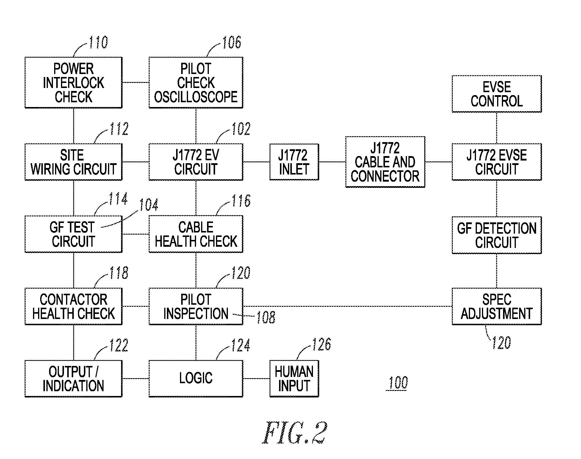
[0046]FIG. 5 shows the wiring check function 112 of FIG. 2. This provides detection and remediation when the EVSE 152 manufacturing, installation, or...
example 2
[0050]One example of the logic 168 of FIG. 5 is as follows.
[0051]If the EVSE state is ReadyToCharge (i.e., the pilot pin 4 of FIG. 1 peak is 6 Vdc), and if the voltage between pin 1 and pin 2 is 120 Vac, and if the voltage between pin 2 and pin 3 is 120 Vac, and the voltage between pin 1 and pin 3 is 0 Vac as determined by the number of voltage sensors 166, then recommend fixes or causes: HOT_AND_NEUTRAL_ARE_REVERSED. This covers the case for a U.S. based single phase 120 Vac system in which Hot1 and neutral are crossed due to a faulty installation or manufacturing. Neutral and ground being reversed cannot be detected.
[0052]Otherwise, if the voltage between pin 1 and pin 2 of FIG. 1 is 230 Vac, and if the voltage between pin 2 and pin 3 is 230 Vac, and if the voltage between pin 1 and pin 3 is 0 Vac as determined by the number of voltage sensors 166, then recommend fixes or causes: HOT_AND_NEUTRAL_ARE_REVERSED. This covers the case for 230 Vac IEC areas using one phase of a three-ph...
example 3
[0062]One example of the logic 168 of FIG. 6 is as follows. This logic 168 is run while a function checks that specified GFCI 180 trip values (for pin 1 and pin 2 of FIG. 1) are not within specification. The logic 168 continually loops back through the logic to make sure that the EVSE 152 is in compliance, attempts to self heal, and if it never gets to the specified values, then exits with instructions to fix the statistically most likely cause of the problem (e.g., the EVSE GFCI 180 (board and CTs)).
[0063]If the EVSE state is CHARGING, which is true when the EVSE relay / contactor 182 is closed, then a function is run that causes a growing variable ground fault and that records the current and time at which the EVSE GFCI 180 detected the ground fault. Since the cause was an intentional ground fault on pin 1 of FIG. 1, which was detected by the EVSE 152, then the logic 168 waits until the EVSE state returns to CHARGING. The next step is to run the same function on pin 2 that causes a ...
PUM
 Abstract
Description
Claims
Application Information
 - R&D
- Intellectual Property
- Life Sciences
- Materials
- Tech Scout
- Unparalleled Data Quality
- Higher Quality Content
- 60% Fewer Hallucinations
Browse by: Latest US Patents, China's latest patents, Technical Efficacy Thesaurus, Application Domain, Technology Topic, Popular Technical Reports.
© 2025 PatSnap. All rights reserved.Legal|Privacy policy|Modern Slavery Act Transparency Statement|Sitemap|About US| Contact US: help@patsnap.com


