Reed and weaving machine for weaving pattern formation in woven fabrics with additional pattern effects

Inactive Publication Date: 2014-07-08
LINDAUER DORNIER GMBH
View PDF81 Cites 3 Cited by
  • Summary
  • Abstract
  • Description
  • Claims
  • Application Information

AI Technical Summary

Benefits of technology

[0010]In an advantageous embodiment, the insertion bevel of the reed blades of the first group pointing in the longitudinal direction of the reed is configured or embodied in such a way that the upwardly facing opening of one or more neighboring open reed gaps and the upper end of one or more neighboring reed blades which belong to the first group are covered at least partially by the insertion bevel. Thereby it is also prevented that the effect threads get stuck on the upper ends of the neighboring reed blades.
[0011]In a particularly advantageous embodiment, the insertion bevel of the first group of reed blades is embodied as a pointedly or sharply tapered tongue-like extension of a reed blade, which is angled in the longitudinal direction of the reed opposite the remaining reed blade. This form or shape is easy to manufacture and guarantees the desired function.
[0012]In the use of effect threads that are significantly coarser than the warp threads of the ground pattern, it is advantageous that the reed gaps that are bounded by a reed blade with insertion bevel, and that are not covered by an insertion bevel, have a greater width in the longitudinal direction of the reed than the reed gaps that are covered by an insertion bevel. Thus, a submerging of the coarser effect threads into the reed gaps provided therefor is facilitated without too greatly impairing the drawing-in of ground warp threads into the reed.
[0013]For the same reason it can be advantageous to provide a greater thickness for the reed blades with insertion bevel in the longitudinal direction of the reed than the reed blades without insertion bevel.
[0014]To get more freedom in the patt

Problems solved by technology

During the submerging of an effect thread into an open reed gap, problems can arise especially with coarser

Method used


Image

  • Reed and weaving machine for weaving pattern formation in woven fabrics with additional pattern effects
  • Reed and weaving machine for weaving pattern formation in woven fabrics with additional pattern effects
  • Reed and weaving machine for weaving pattern formation in woven fabrics with additional pattern effects

Examples


Embodiment Construction

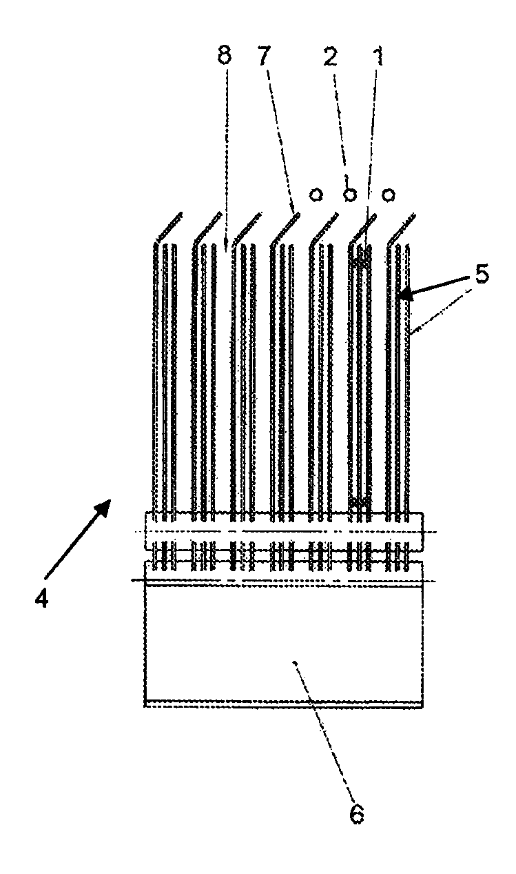
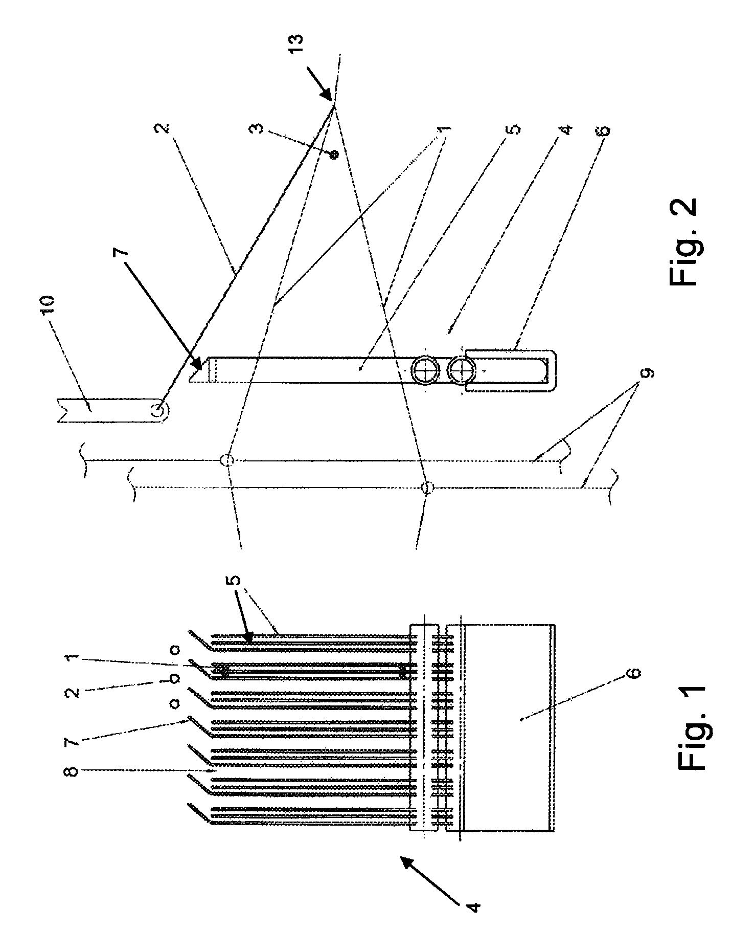
[0021]FIG. 1 shows a reed 4 with reed blades or dents 5, which are combined together at their lower end in a reed base or reed band 6. The manner in which such a reed band 6 is designed or constructed is known to a person skilled in the art and thus does not need to be explained any further in detail. The example embodiment shows an embodiment with a U-shaped profile and two spiral coil springs, in the windings of which the reed blades 5 are inserted. The upper end of the reed blades 5 is left free so that upwardly open reed gaps 8 are formed. Warp threads 1 are drawn into these reed gaps 8. Some of them are located in the upper shed, i.e. at the upper end of the reed blades 5, while others lie in the lower shed near the reed band 6. In the present example these are each respectively drawn into the same reed gap 8. Moreover, effect threads 2 are shown, which in FIG. 1 are located above the warp threads 1 and above the upper ends of the reed blades 5. To facilitate a submerging of th...


PUM


Abstract

For producing woven fabrics with additional pattern effects, one or more effect threads are supplied substantially in the warp direction and are moved over neighboring warp threads in the weft direction, above a weft thread that is to be inserted, in various motion cycles of a weaving machine. Subsequently the effect threads are positioned below a subsequent weft thread, by submerging the effect threads into upwardly open reed gaps of a reed. To facilitate this, the reed includes first reed blades which, at their upper end, each include a sloping thread guide element projecting in the longitudinal direction of the reed, so as to at least partially extend over the upwardly facing opening of a neighboring reed gap. The reed further includes second reed blades having no such sloping thread guide elements. The guide elements guide the effect threads down into the proper reed gaps.

Description

FIELD OF THE INVENTION[0001]The present invention relates to a reed and a weaving machine for weaving pattern formation in woven fabrics with additional pattern effects.BACKGROUND INFORMATION[0002]In weaving machines it is known in the prior art to involve additional threads, which essentially extend in the warp direction, in the woven fabric weave or interlacing in such a manner, so that certain additional pattern effects are achieved. For this purpose, these effect threads are brought into a prescribed position in the weft direction before the insertion of a weft thread for each motion cycle of the weaving machine.[0003]A weaving machine with which such additional pattern effects are produced, includes at least one guide means for one or more effect thread, which is connected with a sliding displacement device. Thereby, the effect threads together with the guide means are slidingly displaceable in the weft direction by a sliding displacement path or distance prescribed by a weavin...

Claims


Application Information

Patent Timeline
IPC IPC(8): D03D49/62D03D47/26D03D49/60D03D49/68
CPCD03D49/68D03C7/06D03D31/00D03D47/263D03D49/62
Inventor WAHHOUD, ADNANCZURA, PETERARNOLD, HARALD
Owner LINDAUER DORNIER GMBH
Why Eureka
Try Eureka