Method for the production of punched parts in web- or sheet-like print substrates and their further processing

a technology of print substrates and parts, applied in the direction of paper/cardboard containers, instruments, paper/cardboard articles, etc., can solve the problems of unattractive punching rings and the possibility of writing

Inactive Publication Date: 2014-07-08
FOFITEC AG
View PDF9 Cites 2 Cited by
  • Summary
  • Abstract
  • Description
  • Claims
  • Application Information

AI Technical Summary

Benefits of technology

[0017]The features, which can be guided precisely in the context of the subsequent processing of the punched parts using the markings punched out in a tolerance-free manner relatively to the punched parts, could also be chip card modules with a semiconductor chip and contacts, wherein the punched parts are again cards or folded cards in the so-called credit card format. Here, the standard ISO 7816-2 determines the position of the contacts of the chip card modules on the cards relatively to their edges. Using the markings according to the invention, the chip card modules can be placed sufficiently accurately on the cards in accordance with this standard. The chip card modules can, as a result and with reuse of the markings according to the invention, even also be written to with information if the cards are still connected to the print substrates. And, due to the exact placing of the chip card modules relatively to the card edges, this information can ultimately also be read again on the detached cards with a standard reading device for chip cards.
[0018]Preferably, the chip card modules are applied as a replacement for a piece of a part layer of the punched parts which is the same shape, wherein the pieces in the punched parts which are the same shape are punched out together with the punching of the punched parts with the punching tool. Using the markings punched out according to the invention at the same time as and in a tolerance-free manner with the pieces which are the same shape, the chip card modules can be placed accurately in the depressions in the punched parts which arise after the removal of the pieces which are the same shape.
[0021]Edges are preferably punched in the print substrates as markings, as edges can be detected easily with optical sensors. The edges are particularly orientated transversely and / or longitudinally to the pass direction in the further tool. In the case of edges orientated transversely to the pass direction, the interruption and / or the finishing of an interruption of a light beam directed perpendicularly onto the print substrates can for example be detected when the edges pass the light beam in the pass. In the case of edges orientated longitudinally to the pass direction, a light beam could be orientated onto these in such a manner that a part of the light beam falls on the printed substrates whilst the remaining part of the light beam reaches a sensor beyond the edges. The orientation of the edges transversely to the pass direction can then be determined from the intensity of the light received by the sensor and this orientation can be corrected dynamically if necessary. The edges orientated in the longitudinal direction do not have to be constructed to be particularly long to this end and particularly do not have to extend uninterruptedly along the entire printed substrate. In the case of web-like print substrates, the markings can as a result be produced by separation from notched edge strips with the punching tool.
[0023]As soon as the method according to the invention, as mentioned previously, for producing print substrates with encoded magnetic strips on the punched parts is used, in the case of web-like print substrates the magnetic strips required to this end can be applied in the same pass with the punching before the punching onto the web-like print substrate in that a material strip provided with a magnetic strip is laminated onto it in a continuous manner. Positioning tolerances of the magnetic strip on the subsequently punched parts in the direction of travel of the print substrate web are dispensed with as a result, in that the magnetic strip extends in any case completely beyond the punched parts in the direction of travel of the print substrate web. Due to the endless process, the magnetic strip is also orientated always exactly parallel to the print substrate web. Positioning tolerances of the magnetic strip transversely to the direction of travel of the print substrate web can be overcome most simply by means of a certain excess width of the magnetic strip. There is no rule which limits the maximum width of the magnetic strip. On the other hand, due to lateral forced guiding means of the material strip carrying the magnetic web, which are mounted fixedly relatively to the punching tool and upstream of the same with only a small spacing, the magnetic strip can likewise be applied very accurately relatively to the punched parts during lamination transversely to the direction of travel of the print substrate web.

Problems solved by technology

That leaves behind unattractive punching rings.
In those forms which are produced with a web finishing method, on account of the positioning tolerances which arise in this case, it has not proven possible to write to the magnetic strip with an encoding in the continuous web or the forms produced therefrom and read this encoding off again at the individual cards with a satisfactory success rate after separating the cards from the continuous web or the forms.

Method used


Image

  • Method for the production of punched parts in web- or sheet-like print substrates and their further processing
  • Method for the production of punched parts in web- or sheet-like print substrates and their further processing
  • Method for the production of punched parts in web- or sheet-like print substrates and their further processing

Examples


Embodiment Construction

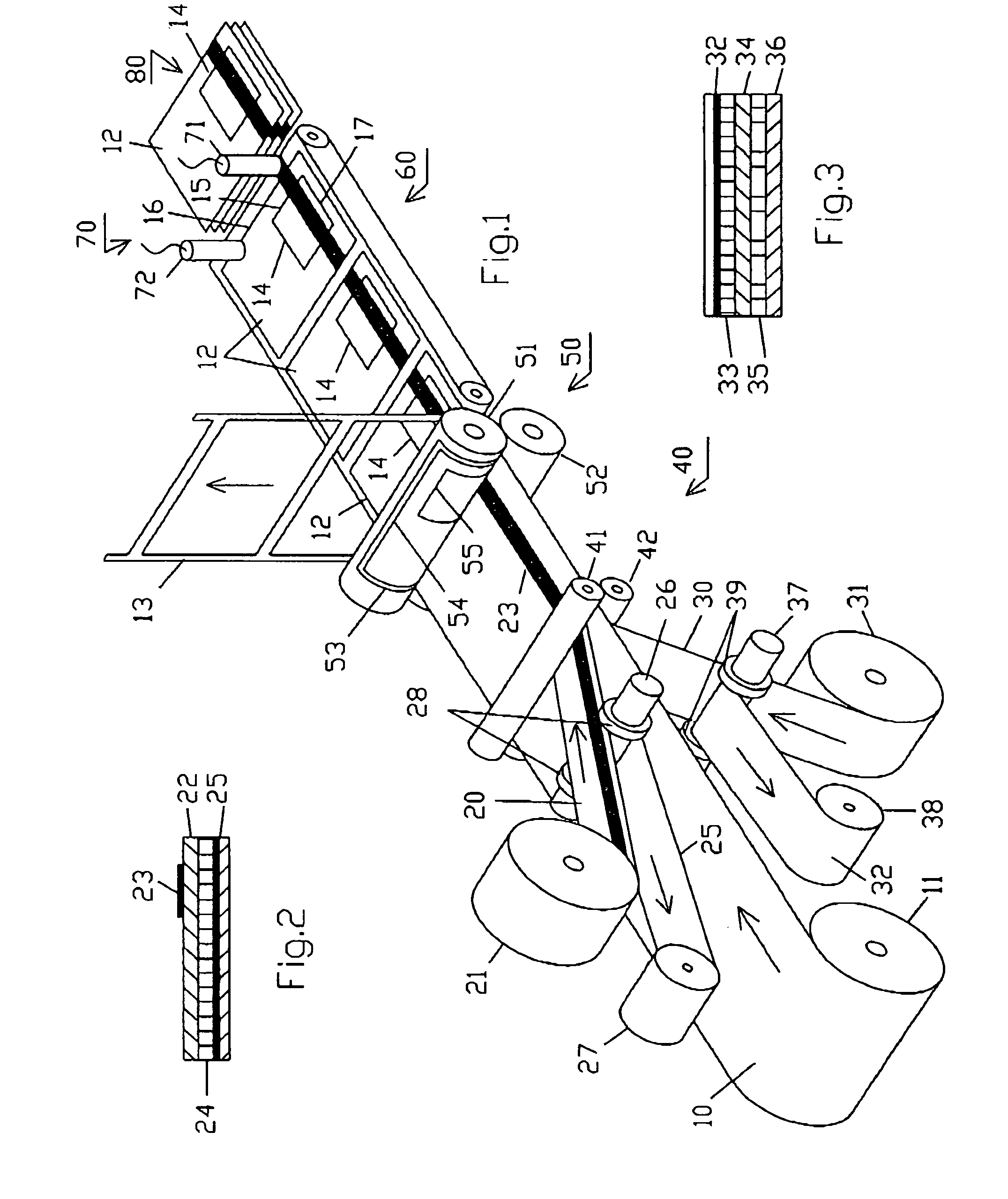
[0032]In the case of the device of FIG. 1, in a laminating station 40, a magnetic strip web 20 is laminated onto the front side and, overlapped with that, a carrier material web 30 is laminated onto the rear side of a printed substrate web 10. The three webs are in each case unwound from rolls 11, 21 and 31 and run through the laminating station 40 between two pressure rolls 41 and 42.

[0033]The magnetic strip web 20 is a multi-layer laminate with a film layer 22 on which a magnetic strip 23 is continuously applied on the front side. On the rear side, the film layer is provided with an adhesive layer 24, by means of which it is adhesively bonded to the print substrate web 10. In order that it can be wound up onto itself, the magnetic strip web 20 on the roll 21 is still covered with a separating paper layer 25, which is pulled off from the adhesive layer 24 upstream of the laminating station 40 by means of a roll 26 and is thereafter wound onto a roll 27. The roll 26 is provided with...


PUM


Abstract

In the case of a method for the production of punched parts in web- or sheet-like print substrates, wherein the punched parts are punched in the pass of the print substrates through a punching tool and thereafter provided in the pass through a further tool with a feature which requires a positioning within predetermined limits on them, it is suggested according to the invention that markings are punched out with the punching tool in the print substrates in each case arranged in a tolerance-free manner in terms of their position relatively to the punched parts and that these markings are used in the subsequent processing of the punched parts for guiding the feature mentioned.

Description

BACKGROUND OF THE INVENTION[0001]1. Field of the Invention[0002]The present invention relates to a method for the production of punched parts in web- or sheet-like print substrates, wherein the punched parts are punched in the pass of the print substrates through a punching tool and thereafter provided in the pass through a further tool with a feature which requires a positioning within predetermined limits on them.[0003]The invention also relates to web-like print substrates or stacks of sheet-like print substrates as products of this method.[0004]The invention also relates to web-like print substrates or stacks of sheet-like print substrates as products of this method.[0005]2. Description of the Prior Art[0006]Methods of the previously mentioned type are known in various configurations, among which the so-called web finishing methods are also to be counted.[0007]In web finishing, self-adhesive pieces of material (patches) made from paper and / or film are affixed in a pass to a, for...

Claims


Application Information

Patent Timeline
Patent Type & Authority Patents(United States)
IPC IPC(8): G06K19/06
CPCB31D1/021G06K19/07722G06K19/06187B26F1/384B42D5/027G06K19/07718B26F1/12G06K1/125B42D25/475B26D5/36B42D25/00B42D2031/30B42D15/10B42D25/48
Inventor FISCHER, JULES
Owner FOFITEC AG
Why Eureka
Try Eureka