Drying apparatus under reduced pressure for plastic molding material

a technology of plastic molding material and drying apparatus, which is applied in lighting and heating apparatus, separation processes, manufacturing tools, etc., can solve the problems of inability to discharge molding material from the lower end, inability to stably discharge plastic molding material, and inability to discharge molding material, etc., to prevent short-pass phenomenon of material and adherence, and prevent the effect of adherence of plastic molding materials

Inactive Publication Date: 2014-07-15
MATSUI MFG
View PDF36 Cites 54 Cited by
  • Summary
  • Abstract
  • Description
  • Claims
  • Application Information

AI Technical Summary

Benefits of technology

[0014]In the drying apparatus under reduced pressure of the present invention, gas stored in the gas tank is instantaneously charged in the drying hopper in depressed state from the gas charge port, so that a plastic molding material stored in the drying hopper can be moved so as to be entirely lifted up by resistance against instantaneous flow of gas, thereby achieving an effect of preventing short-pass phenomenon of material and adherence of plastic molding materials each other.
[0015]In the drying apparatus under reduced pressure for a plastic molding material of the present invention, the gas tank can be designed to have the gas changeover valve with three connection ports, a first one can be always connected to the gas tank, a second one can be connected to the gas pressure regulation valve connected to the gas supply port via an on-off valve, and a third one can be connected to the gas charge port via an on-off valve. In normal drying conditions, gas which is controlled to have predetermined volume by opening the on-off valve of the gas pressure regulation valve and closing the on-off valve of the gas charge port is stored in the gas tank. After predetermined time, gas which is stored under pressure at predetermined volume by closing the on-off valve of the gas pressure regulation valve and opening the on-off valve of the gas charge port is charged to the drying hopper, thereby preventing adherence of plastic molding materials each other while keeping in depressurized state in the drying hopper.
[0016]In addition, if control is executed such that the vacuum pump is stopped when gas stored in the gas tank is charged in the drying hopper, the gas stored in the gas tank can be charged to the drying hopper rapidly and effectively.

Problems solved by technology

However, such a ventilation type drying method which discharges heated air introduced in the dryer to factories is not good for environment, therefore, recently there has been a method of drying a plastic molding material by heat transmission and of evacuating generated moisture out of the system by further vacuumizing and such a method is used as a method which does not release heated air introduced in the dryer therefrom.
As a result, there have been such problems that the plastic molding material comes to adhere to the heat transfer fin and the plastic molding materials come to adhere each other, thereby being unable to be discharged from the lower end, namely the plastic molding material cannot be discharged from the drying hopper, and the plastic molding material cannot be stably discharged.
However, vibration and impact on a machine apply burdens the machine and crack it, and makes unable to execute first-in first-out discharge of a plastic molding material, thereby such a method is inappropriate for continuous processing.
In addition, in case of vacuum drying, application of vibration and impact causes leak and sufficient effects cannot be obtained.
However, in such a method, drying time for a plastic molding material in the drying hopper cannot be controlled in a circulation line for returning the discharged plastic molding material to the dryer, and failure is caused by over-dried materials and energy is wasted.

Method used


Image

  • Drying apparatus under reduced pressure for plastic molding material
  • Drying apparatus under reduced pressure for plastic molding material
  • Drying apparatus under reduced pressure for plastic molding material

Examples


Embodiment Construction

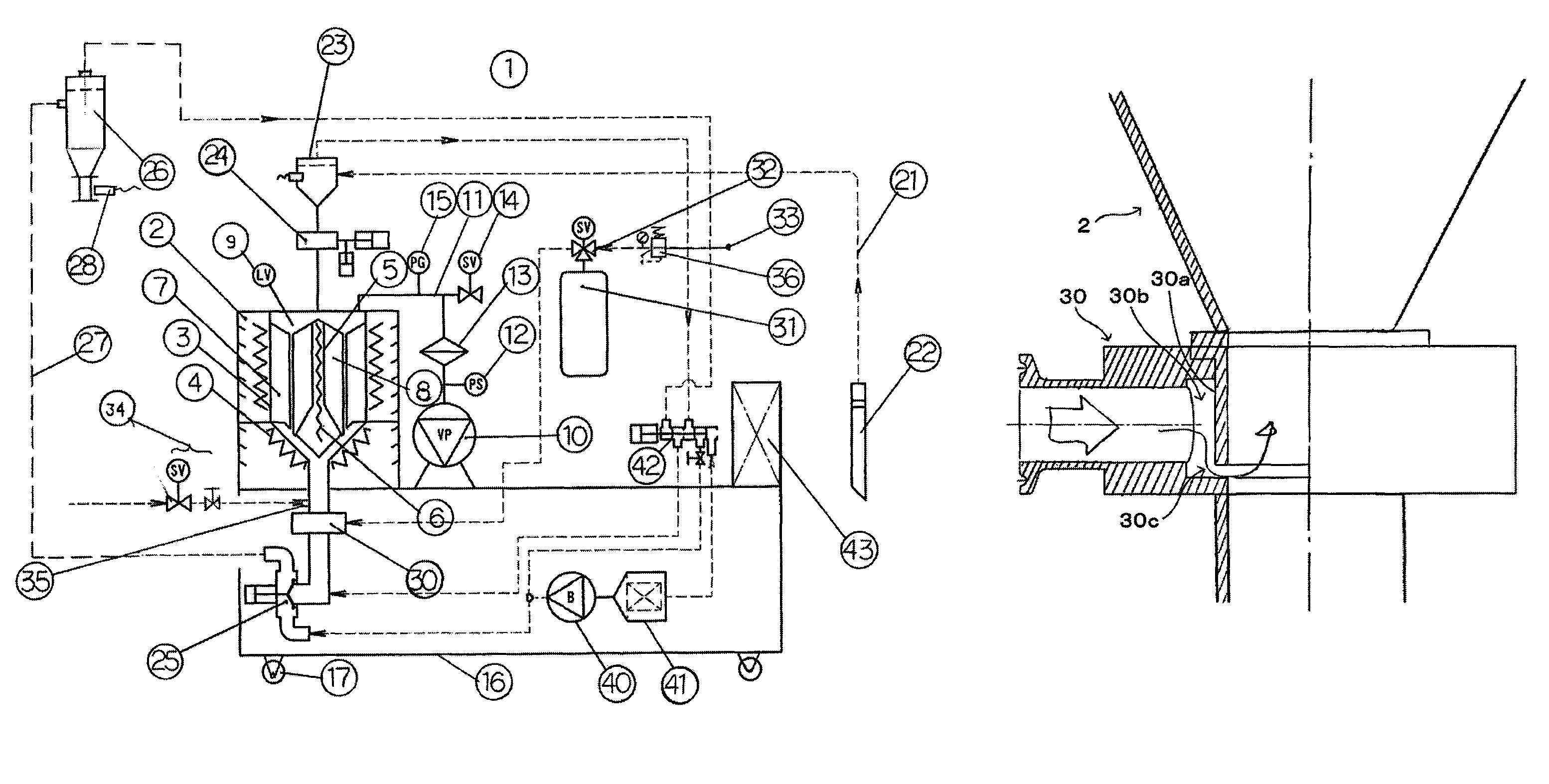
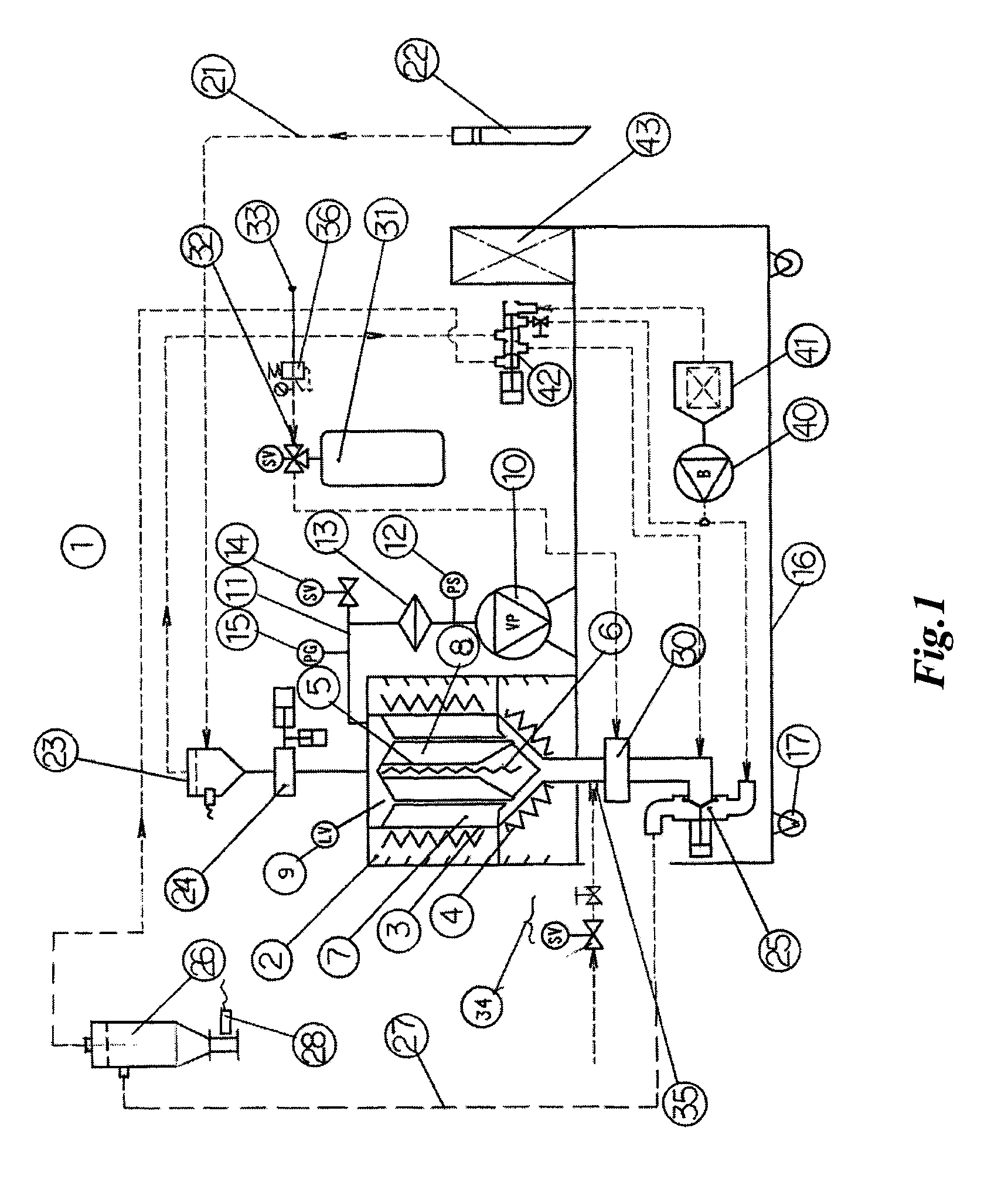
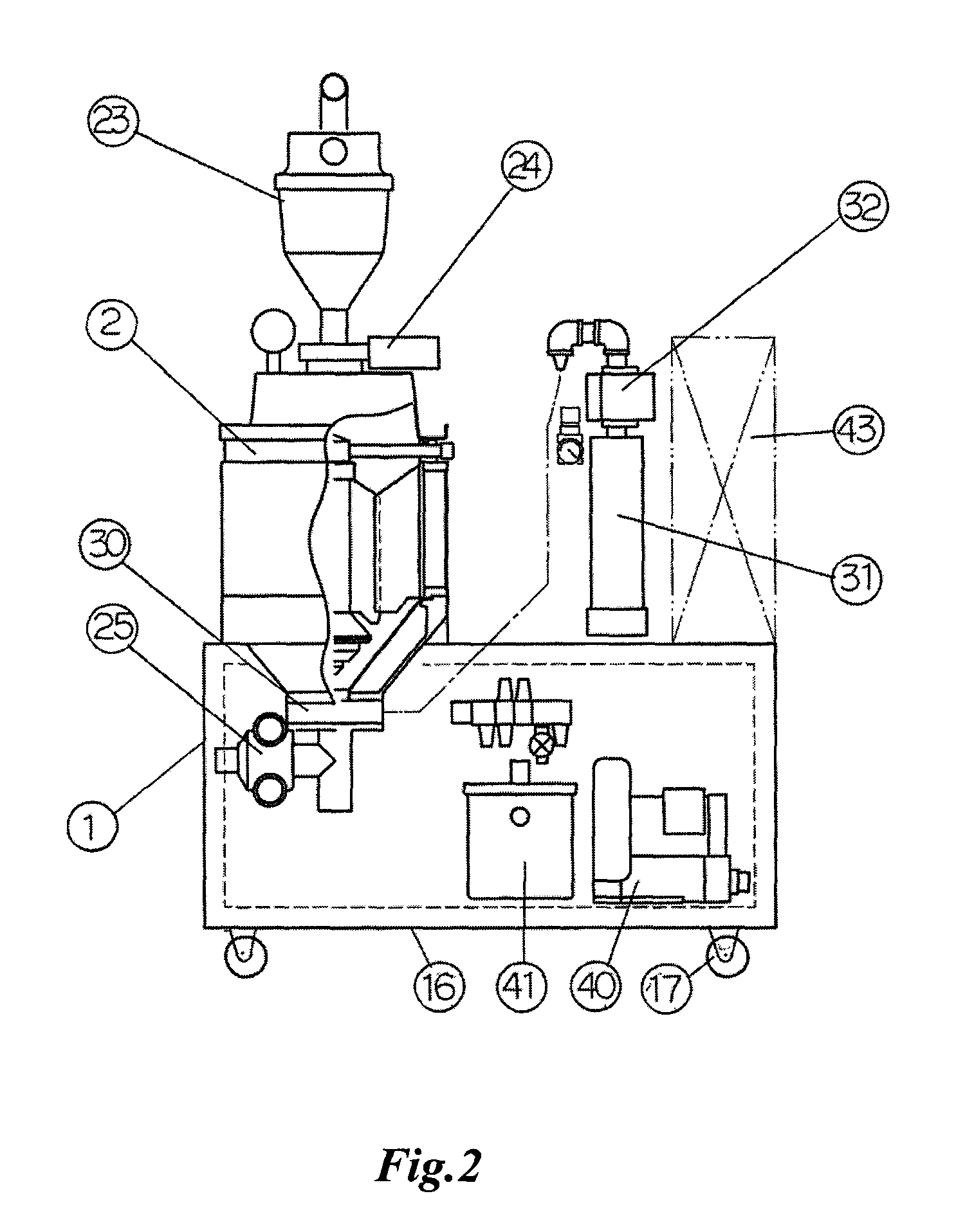
[0020]One embodiment of a drying apparatus under reduced pressure for a powdered or granular material according to the present invention is explained referring to the drawings. FIG. 1 is one embodiment of a drying apparatus under reduced pressure for a plastic molding material having an adherence preventing means according to the present invention and shows a system diagram of the entire structure when it is used for plastic molding. FIG. 2 shows an external view of a main body of the drying apparatus under reduced pressure according to the embodiment of the present invention and is a front view a part of which is cut out. FIG. 3 is a detailed view of a gas charge port.

[0021]A drying apparatus under reduced pressure 1 shown in FIG. 1 is a floor model, in which a thermal conduction wall 3 made of material with high thermo-conductivity such as aluminum and the like is provided at the outer circumferential portion in a drying hopper 2 and an outer-side heating means 4 constituted with ...


PUM

PropertyMeasurementUnit
pressureaaaaaaaaaa
vacuum pressureaaaaaaaaaa

Abstract

A drying apparatus under reduced pressure for a plastic molding material. The apparatus comprises a drying hopper provided with an airtight material charge valve capable of containing gas therein at its upper portion and a material discharge valve at its lower portion, and connected to a vacuum pump via vacuum piping, a heating means of thermal conduction type provided in the drying hopper, and a plastic material adherence preventing means in which a gas charge port connected to a gas tank storing gas via a gas changeover valve is provided between the material discharge valve and the drying hopper and stored gas is fed into the drying hopper by opening the gas changeover valve after predetermined time, thereby preventing adherence of plastic molding material.

Description

TECHNICAL FIELD[0001]The present invention relates to a drying apparatus under reduced pressure having an adherence preventing means for a plastic molding material.BACKGROUND ART[0002]In case of drying a plastic molding material such as pellets or pulverized materials before molding, a method using a ventilation type dryer has been conventionally adopted. The ventilation type drying is such a method that a charge port for a plastic molding material is provided on the dryer and a discharge port is provided under the dryer, heated air heated to predetermined temperature is introduced under the dryer to ventilate upwardly, and a plastic molding material is heated and dried. However, such a ventilation type drying method which discharges heated air introduced in the dryer to factories is not good for environment, therefore, recently there has been a method of drying a plastic molding material by heat transmission and of evacuating generated moisture out of the system by further vacuumiz...

Claims


Application Information

Patent Timeline
Patent Type & Authority Patents(United States)
IPC IPC(8): F26B17/12
CPCB29C35/045F26B5/042Y10T428/131B29C2035/046B29B13/065
Inventor HANAOKA, KAZUNARINAKAGAWA, JUNJI
Owner MATSUI MFG
Why Eureka
Try Eureka