Adaptable basement window frame system

Inactive Publication Date: 2014-07-15
THEOPHILUS MORGAN F
View PDF41 Cites 16 Cited by
  • Summary
  • Abstract
  • Description
  • Claims
  • Application Information

AI Technical Summary

Benefits of technology

[0007]A window frame system having a window frame and cavity frame formed to frictionally fit within the window frame. An opening is cut in a wall based on measurements of the cavity frame, and the ends of the cavity frame are

Problems solved by technology

This is virtually impossible to do when cutting a cavity into an existing concrete or masonry wall.
Al

Method used


Image

  • Adaptable basement window frame system
  • Adaptable basement window frame system
  • Adaptable basement window frame system

Examples


Embodiment Construction

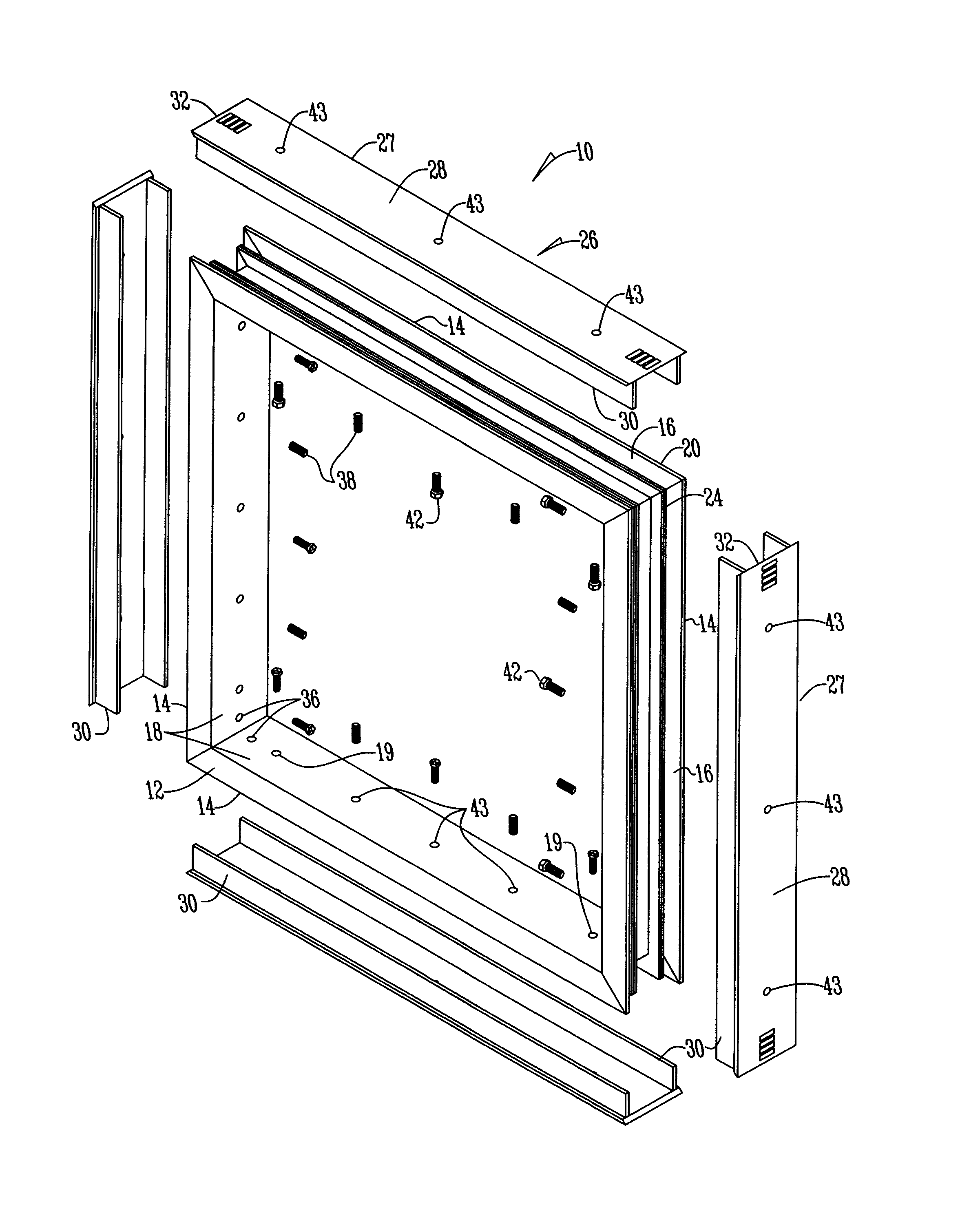
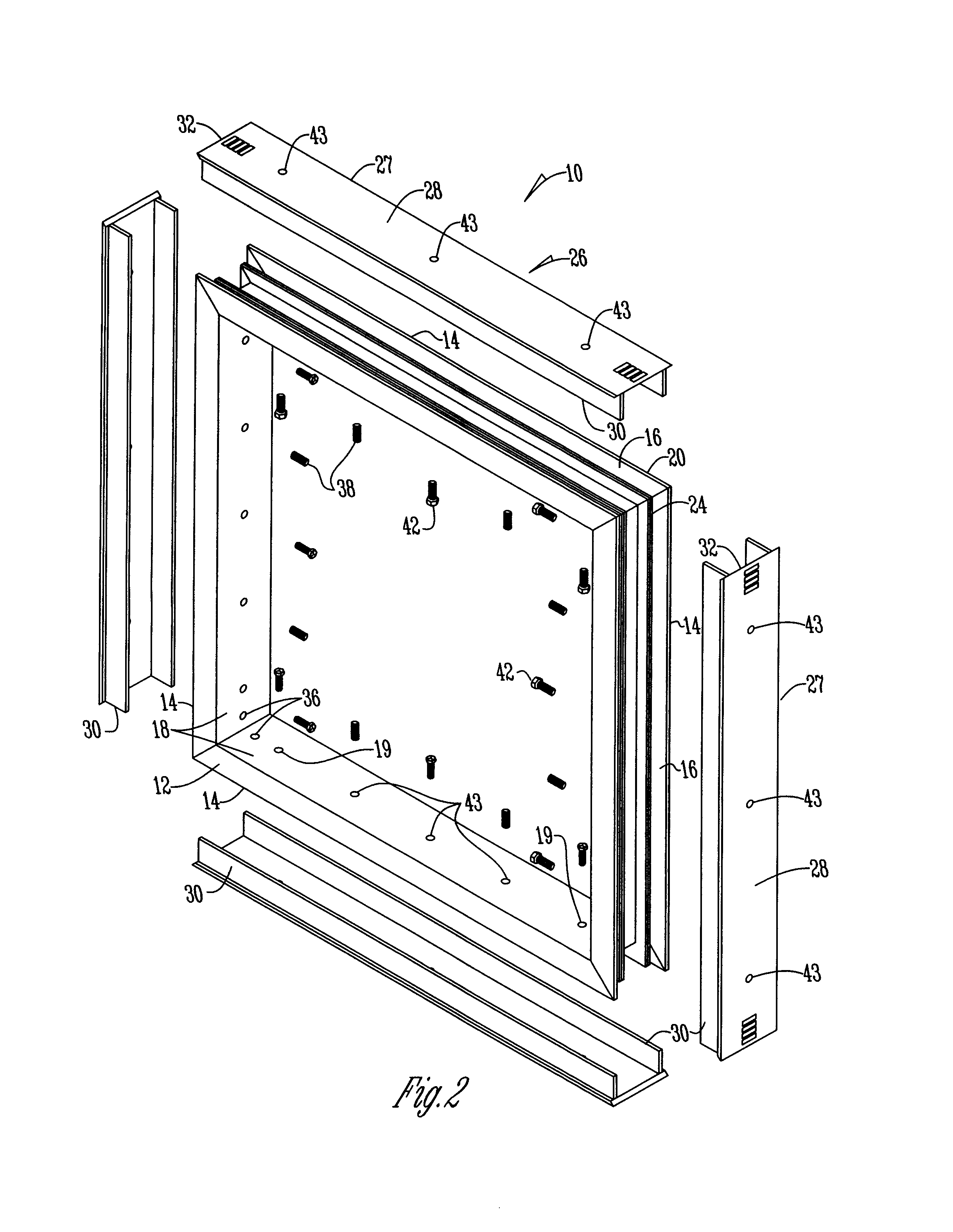
[0011]Referring to FIG. 2, the frame system 10 includes a window frame 12 having four elongated members 14 that are joined at their corners to form a square or rectangle and cavity frame 26. The frame system 10 is made of any material but preferably is made of PVC or the like. Each elongated member 14 has an inner surface 16 and an outer surface 18. At least one and preferably a plurality of holes 19 and 43 are positioned along the inner surface of frame 12. The outer surface 18 has two outwardly extending flanges 20 which form a web or channel 22 as shown in FIG. 3. In a preferred embodiment, disposed within the web 22 and extending along the outer surface 18 is a stiffener 24. The stiffener 24 is free standing, attached to the frame 12, or is molded as part of the frame 12.

[0012]A cavity frame 26 has four elongated members 27 with each having two side walls 30 as shown in FIG. 2. The side walls 30 are preferably positioned inwardly from the edge of the outer wall 28 and are genera...


PUM


Abstract

A window frame system having a window frame and cavity frame formed to frictionally fit within the window frame. An opening is cut in a wall based on measurements of the cavity frame, and the ends of the cavity frame are trimmed based upon the opening cut in the wall. Jack screws are inserted through holes in the window frame to center and level the system by pushing the cavity frame away from the window frame to engage the edges of the opening.

Description

BACKGROUND OF THE INVENTION[0001]This invention is directed toward a window for installation in a basement and more particularly to a window frame that is adaptable for installation in a basement. Homeowners install basement windows ranging in size from 3′×4′ to 5′×6′ in their lower living areas to meet the egress requirements for residential building codes. Basement windows require a frame to be sized and squared within an opening by approximately ⅛ of an inch. This is virtually impossible to do when cutting a cavity into an existing concrete or masonry wall. The current practice is to cut the hole and then construct a wood frame that is the proper size and square. The frame is then shimmed to fit the cavity and attached to the cavity walls with concrete fasteners. Then the window is mounted to either to room side or exterior outside of the wooden frame with an integral nailing fin. Insulation foam is used to fill both between the window frame and the cavity and the wood frame and ...

Claims


Application Information

Patent Timeline
IPC IPC(8): E06B3/667E06B3/54E06B1/56E06B1/02
CPCE06B5/02E06B3/667E06B1/26E06B1/02E06B3/5454E06B1/603
Inventor THEOPHILUS, MORGAN, F.
Owner THEOPHILUS MORGAN F
Why Eureka
Try Eureka