Construction method of dewatering well under foundation slab in foundation pit

A foundation base plate and construction method technology, applied in the direction of basic structure engineering, excavation, construction, etc., can solve the problem of increasing the depth of precipitation well layout, precipitation time and precipitation range, and waterproof effect. To achieve the effect of convenient construction, increased adverse effects, and simple layout

Active Publication Date: 2010-05-12
南通建工集团股份有限公司
View PDF0 Cites 43 Cited by
  • Summary
  • Abstract
  • Description
  • Claims
  • Application Information

AI Technical Summary

Problems solved by technology

The general dewatering method is to arrange multiple dewatering wells in the foundation pit. The downwater pipe and its cable line pass through the foundation structure through the casing and other corresponding waterproof treatment measures, and are discharged outside the foundation pit. After meeting the requirements for stopping dewatering, the dewatering The foundation structure casing that the well passes through is waterproofed and rigidly sealed; this dewatering construction method, although meeting the dewatering requirements of deep foundation pit operations, affects the waterproof construction quality of the foundation structure, even if the waterproof effect of the casing can be guaranteed, but The guarantee of its waterproof effect depen

Method used


Image

  • Construction method of dewatering well under foundation slab in foundation pit
  • Construction method of dewatering well under foundation slab in foundation pit
  • Construction method of dewatering well under foundation slab in foundation pit

Examples


Embodiment Construction

[0021] A construction method for a foundation floor drop well in a foundation pit, comprising the following steps:

[0022] 1) Dewatering wells 2 are arranged in the foundation pit 1;

[0023] 2) During the excavation of the foundation pit, the dewatering well is not damaged to ensure the effectiveness of the dewatering well;

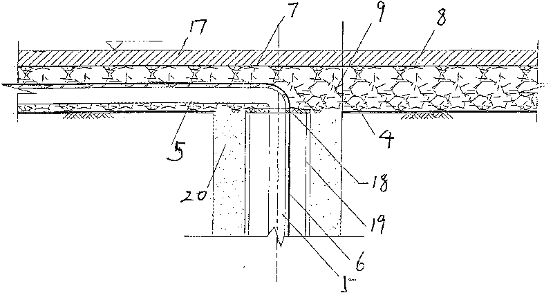
[0024] 3) After excavating the earthwork of the foundation pit to the base, excavate criss-cross trenches 3 along the center line of the dewatering well, and lay water-filtering geotextiles 4 in the trenches; Lay it in the trench and connect it to the outside of the pit, check the depth of the dewatering well, the pump and its pipeline to ensure its integrity and reliability; then lay granular gravel or pebbles 7 in the trench, and cover it with linoleum 8 to form a blind ditch 9. The blind ditch is connected to the side sump 10 of the foundation pit, and the drainage ditch 11 is arranged around the foundation pit;

[0025] 4) The underlayment and wat...


PUM


Abstract

The invention discloses a construction method of a dewatering well under a foundation slab in a foundation pit, comprising the following steps of: arranging the dewatering well in the foundation pit, wherein the dewatering well is not damaged in the process of excavating a foundation pit earthwork, and the effectiveness of the dewatering well is ensured; after the foundation pit earthwork is excavated to a basement, excavating interlaced ditches along the center line of the dewatering well, and paving water-filtering type geotextile in the ditches; then paving drain pipes of the dewatering well and cables in the ditches and connecting to the outside of the pit, checking the depth of the dewatering well, an extraction pump and a pipeline thereof to ensure the integrality and the reliability; then paving granular crushed stones or cobbles in the ditches, covering asphalt felt thereon to form a blind ditch; leading the blind ditch to a water collection pit at the edge of the foundation pit and arranging a surface drain on the periphery of the foundation pit; paving a subcrust and a waterproof layer under the constructed foundation slab, gradually reducing the usage quantity and the dewatering speed of dewatering wells in the foundation pit in the construction process of underground structures and upper structures thereof, and assisting in draining by adopting the water collection pit at the periphery of the foundation pit until the dewatering operation in the foundation pit can be stopped. The invention has convenient construction, safety and reliability and low cost for dewatering in the foundation pit.

Description

Technical field: [0001] The invention relates to a construction method for a foundation floor descending well in a foundation pit. Background technique: [0002] With the rapid development of the development and utilization of underground space, ultra-deep and ultra-wide foundation pit projects are constantly emerging. The drainage measures and their reliable effects in ultra-large deep foundation pits rich in groundwater, especially affected by underground confined water, are the key to ensure deep It is one of the important construction measures to ensure the safety of foundation pit operation and ensure the quality of the project. The general dewatering method is to arrange multiple dewatering wells in the foundation pit. The downwater pipe and its cable line pass through the foundation structure through the casing and other corresponding waterproof treatment measures, and are discharged outside the foundation pit. After meeting the requirements for stopping dewatering, t...

Claims


Application Information

Patent Timeline
IPC IPC(8): E02D19/10E02D19/20E02D17/02
Inventor 张向阳易兴中刘旭张喜一王金峰
Owner 南通建工集团股份有限公司
Why Eureka
Try Eureka