Basement water drainage system

a drainage system and basement technology, applied in the direction of foundation engineering, artificial islands, special buildings, etc., can solve the problems of not being able to adapt to varying construction conditions, not being able to prevent the occurrence of condensation on the peripheral edges of cement floors, and being relatively expensive to manufacture, so as to achieve less complicated and less expensive

Inactive Publication Date: 2005-09-22
MATTHEWS JOHN B
View PDF13 Cites 43 Cited by
  • Summary
  • Abstract
  • Description
  • Claims
  • Application Information

AI Technical Summary

Benefits of technology

[0011] Also, being manufactured in two independent pieces, not only can the sizes of the vertical wall portion be varied, but the separate

Problems solved by technology

While this prior art system is effective it has shortcomings in that it is relatively expensive to manufacture and is not readily adjustable or adap

Method used


Image

  • Basement water drainage system
  • Basement water drainage system
  • Basement water drainage system

Examples


Embodiment Construction

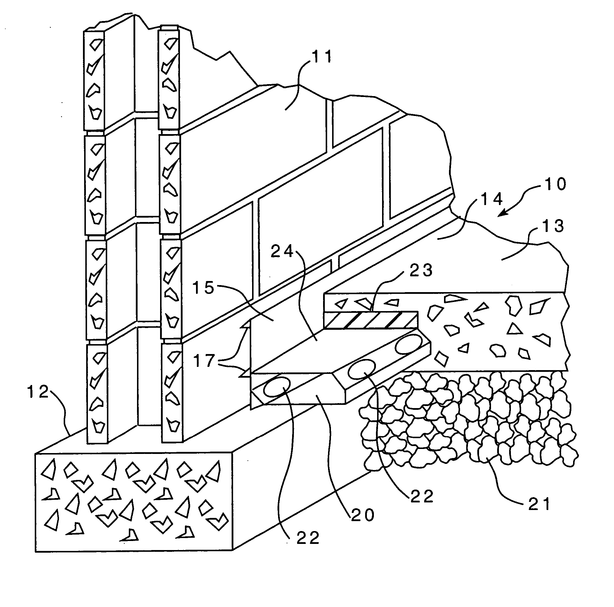
[0017] Referring to FIG. 1, the two-piece ground water drainage conduit system 10 of the present invention is provided for an interior subterranean wall 11 supported on footing 12 and further having a concrete floor 13 with a peripheral edge 14 supported on the footing 12.

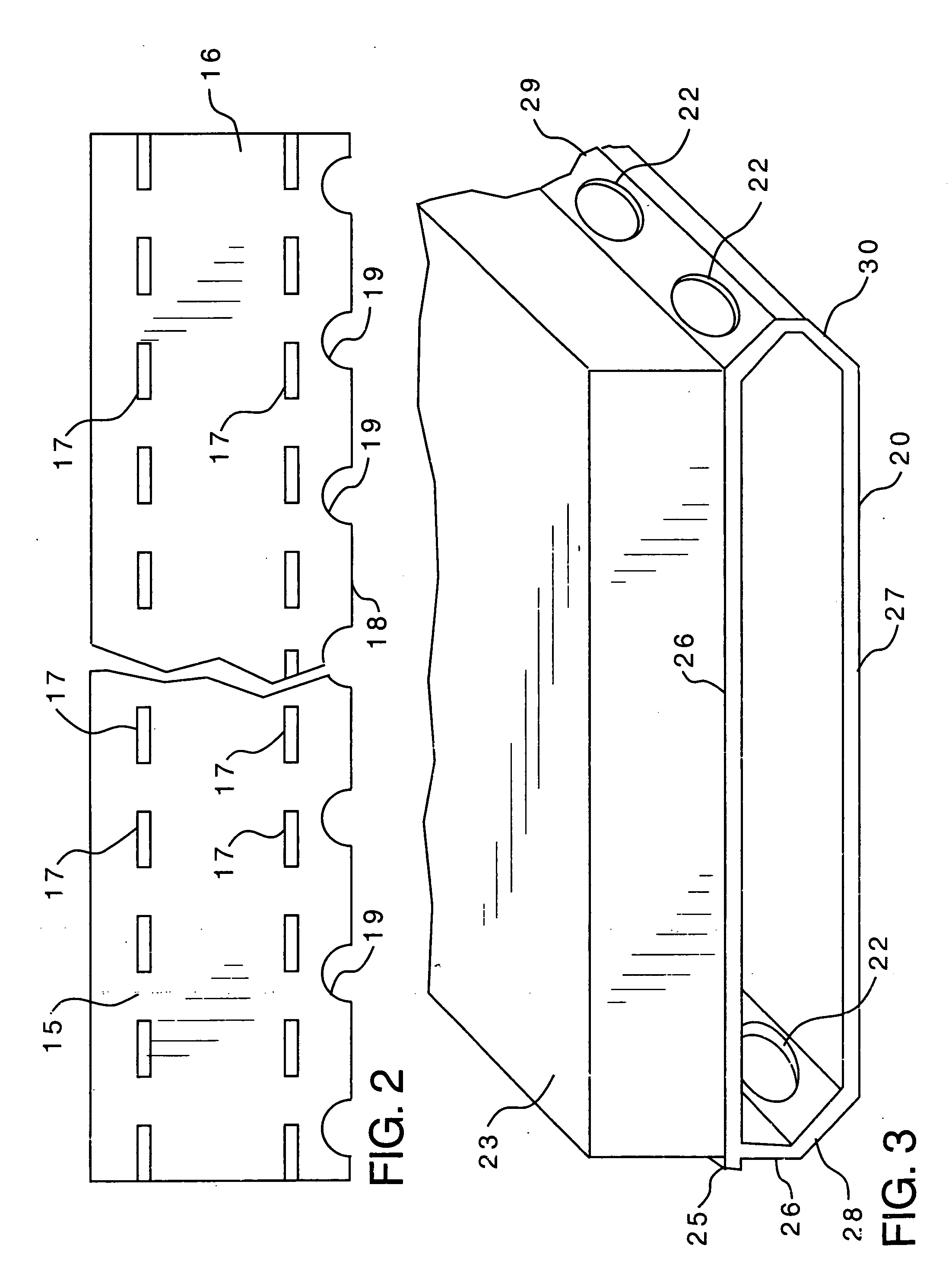
[0018] The two-piece conduit system of the present invention is comprised of a vertical wall portion 15 which extends horizontally and is disposed between the wall 11 and the floor 13. The rear surface 16 (see FIG. 2) of vertical wall portion 15 is provided with spacer protrusions 17 for engagement with the wall 11 whereby a narrow drainage passage is provided therebetween. The height of vertical wall portion 15 is dimensioned such that it extends above the floor 13. In this embodiment, the vertical wall portion 15 rests directly on top of footing 12 and the bottom edge 19 of vertical wall portion 15 is provided with spaced apertures 19 for passing ground water.

[0019] The second piece of the drainage conduit syst...


PUM


Abstract

A two-piece ground water drainage conduit system for interior subterranean walls supported on a footing with a concrete floor having a peripheral edge supported on the footing. The conduit system includes a vertical wall portion that horizontally extends for disposition between the wall and the floor. This vertical wall portion is provided with a rear surface that has spacer protrusions for engagement with the wall to provide a narrow drainage passage therebetween and the vertical wall portion is dimensioned for extension above the floor. The second piece of the system consists of an independent horizontal conduit portion which is positioned adjacent and along the vertical wall portion under the floor periphery and the drain is provided with apertures therealong for admitting ground water from the vertical wall portion narrow drainage passage and from elsewhere. A layer of insulation is applied to the upper exterior surface of the horizontal conduit portion for disposition between the conduit portion and the floor whereby condensation is prevented from forming on the peripheral edges of the floor.

Description

BACKGROUND OF THE INVENTION [0001] The present invention relates to improvements in basement water drainage systems for receiving and channeling ground water from beneath the floor of basement rooms. [0002] Ground water seeps into basements from the walls and from joints at the perimeter of the floor. The present invention relates to improvements in sub-floor drain conduit systems of the type disclosed in U.S. Pat. No. 5,505,044. This patent discloses a sub-floor basement water control system which includes an elongate water receiving conduit designed to be installed at the wall and footing interface, beneath a peripheral area of the basement floor. The conduit is open to receive water admitted through bore holes in a concrete block wall and from the joint between the wall and the footing. The conduit also receives water which passes through openings on the inside surface of the wall, such as cracks, holes and the porosity of the masonry wall itself whereby the conduit can move the ...

Claims


Application Information

Patent Timeline
IPC IPC(8): E02D19/00E02D31/02
CPCE02D31/02
Inventor MATTHEWS, JOHN B.
Owner MATTHEWS JOHN B
Why Eureka
Try Eureka