Sliding valve aspiration

a sliding valve and valve aspiration technology, applied in the direction of oscillatory sliding valves, mechanical equipment, machines/engines, etc., can solve the problems of premature valve failure and reduced sealing, and achieve the effect of reducing valve lash, reducing friction, and increasing engine speed

Active Publication Date: 2014-07-15
GRACE CAPITAL PARTNERS
View PDF37 Cites 10 Cited by
  • Summary
  • Abstract
  • Description
  • Claims
  • Application Information

AI Technical Summary

Benefits of technology

[0020]All intake and exhaust gas flow is thus confined within the tubular interior of the sliding valves. As a result, gas pressure does not develop a substantial resistive force upon leading surfaces of the valve in a direction coincident with the direction of valve travel. Instead gas pressure that might otherwise resist valve travel, and add to friction, is applied as a shear force, and pressure is evenly distributed in the relief annulus. Gas flow is distributed through the valve interior rather than around it, and friction is substantially reduced.
[0031]A still further object is to provide a valve system of the character described that is driven externally by a belt, so that efficiency is increased and complexity is reduced.

Problems solved by technology

However, in the past, large sliding valve ports have contributed to inefficiency, reduced sealing, and premature valve failure.

Method used


Image

  • Sliding valve aspiration
  • Sliding valve aspiration
  • Sliding valve aspiration

Examples


Embodiment Construction

[0067]For purposes of providing an enabling disclosure, prior U.S. patent application Ser. No. 13 / 443,077, Filed Apr. 10, 2012, entitled Sliding Valve Aspiration, by inventor Gary W. Cotton, and U.S. Pat. No. 8,210,147 issued Jul. 3, 2012, Entitled “Sliding Valve Aspiration System,” by inventor Gary W. Cotton, are hereby incorporated by reference as if fully set forth herein.

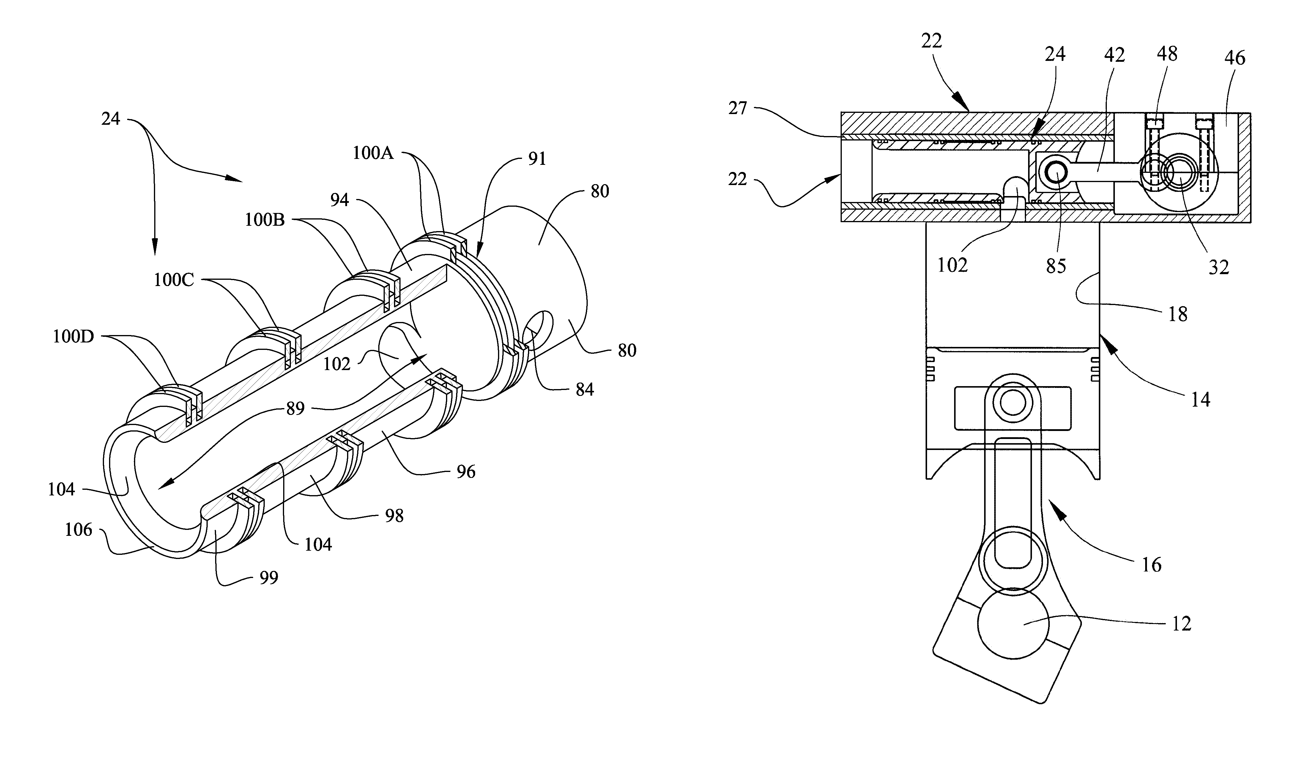
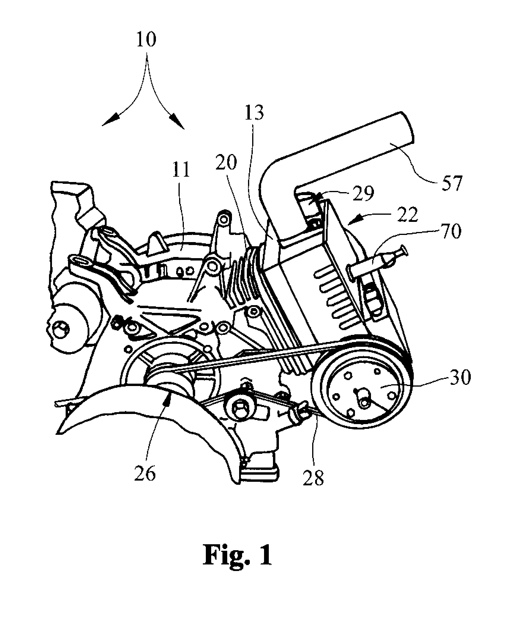
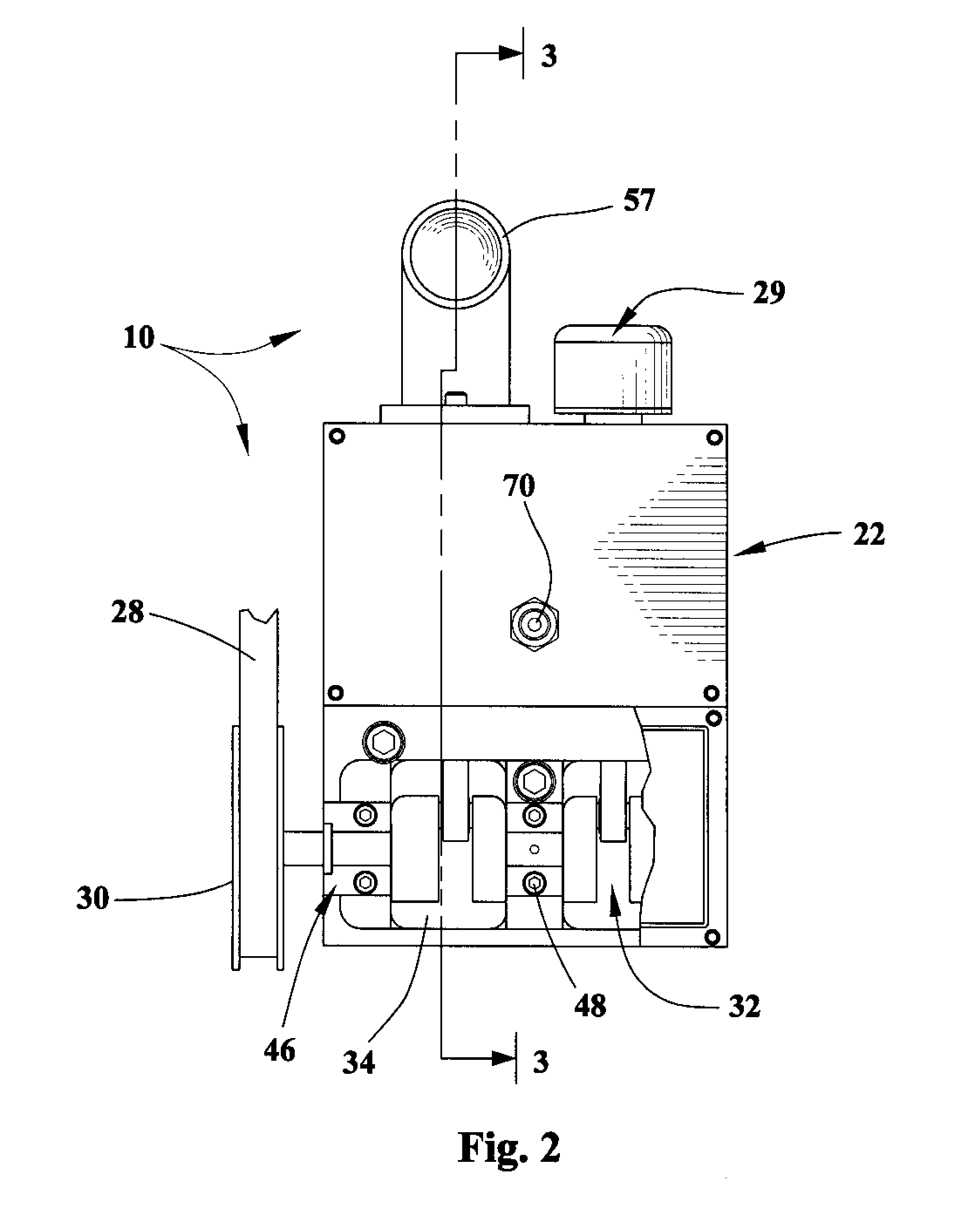
[0068]With initial reference directed to FIGS. 1-5 of the appended drawings, a basic single-cylinder, four-cycle internal combustion engine equipped with the aspiration system constructed in accordance with the best mode of the invention has been generally designated by the reference numeral 10. It should be understood that the aspiration system as herein described is suitable for use with engines equipped with multiple cylinders, arrayed in the popular V-configuration or other configurations. The engine 10 has a rigid block 11 housing a primary crankshaft 12 (FIG. 3) of conventional construction that drives a r...


PUM


Abstract

Multi-section sleeve valves for internal combustion engines for improved aspiration. An open connecting rod section is separated from an internal, tubular passageway by a closed wall. A port section proximate the wall defines valve ports. A power stroke midsection borders the port section. An oiling section borders the midsection, and an open section adjacent the oiling section is in fluid flow communication with the tubular passageway. The lower-diameter midsection forms a relief annulus between the valve and the tunnel or sleeve in which the valve is disposed. Fluid flow occurs through the valve interior and through ports dynamically positioned above the compression cylinder, proximate aligned sleeve and head ports. Sleeve ports are separated by bridges that maintain valve rings in compression during reciprocation to prevent damage. High pressure gas is confined between axially spaced apart, stepped sealing rings that prevent gases from flowing axially about the valve exterior.

Description

CROSS REFERENCE TO RELATED APPLICATIONS[0001]This utility patent application is a Continuation in Part of Ser. No. 13 / 443,077, Filed Apr. 10, 2012, entitled “Sliding Valve Aspiration,” by inventor Gary W. Cotton, which was a divisional application based upon prior U.S. utility patent application Ser. No. 12 / 387,184, filed Apr. 29, 2009, Entitled “Sliding Valve Aspiration System,” by inventor Gary W. Cotton, now U.S. Pat. No. 8,210,147 issued Jul. 3, 2012, which was based upon a prior U.S. Provisional application entitled “Sliding Valve Aspiration Engine,” Ser. No. 61 / 135,267, filed Jul. 18, 2008, by inventor Gary W. Cotton.BACKGROUND OF THE INVENTION[0002]1. Field of the Invention[0003]The present invention relates generally to sleeve valve systems for aspirating internal combustion engines, and to internal combustion engines with tubular sliding valves for enhanced aspiration. More particularly, the present invention relates to reciprocating sleeve valve systems for engines equippe...

Claims


Application Information

Patent Timeline
Patent Type & Authority Patents(United States)
IPC IPC(8): F01L5/00
CPCF01L1/26F01L11/02F01L7/16F01L2820/01F01L7/14F01L7/02F01L5/04F01L2101/00F01L5/00F01L1/053F01L2250/04F01L2250/02F01L2301/00
Inventor COTTON, GARY, W
Owner GRACE CAPITAL PARTNERS
Why Eureka
Try Eureka