Maintaining shale stability by pore plugging
a technology of pore plugging and shale, which is applied in the direction of drilling machines and methods, chemistry apparatus and processes, and wellbore/well accessories, etc., can solve the problems that the pore plugging of shale has not been achieved, and achieve the effect of reducing the permeability of shale and reducing the fluid invasion into the shal
- Summary
- Abstract
- Description
- Claims
- Application Information
AI Technical Summary
Benefits of technology
Problems solved by technology
Method used
Image
Examples
example 2
Atoka Shale
[0077]The Atoka Shale was selected for study using nanoparticles. As part of the standard procedure, samples of the Atoka share were placed in the 0.98 relative humidity desiccator, so as to fix their water activity before testing. While awaiting shale equilibrium, a third study was performed using two, 1 inch by ½ inch by ½ inch, pieces of C3 shale and a Swell Meter. In these tests, one sample was immersed in water and the second sample was immersed in a 41 wt % dispersion of 20 nm particles.
[0078]As shown in FIG. 5, after about 18 hours, the C3 shale that was immersed in the water had experienced about 10.8% swelling and the nanoparticle dispersion experienced only 6.4% swelling, a 41% reduction. These results are the first time swelling was reduced in a shale by a simple water plus solids dispersion.
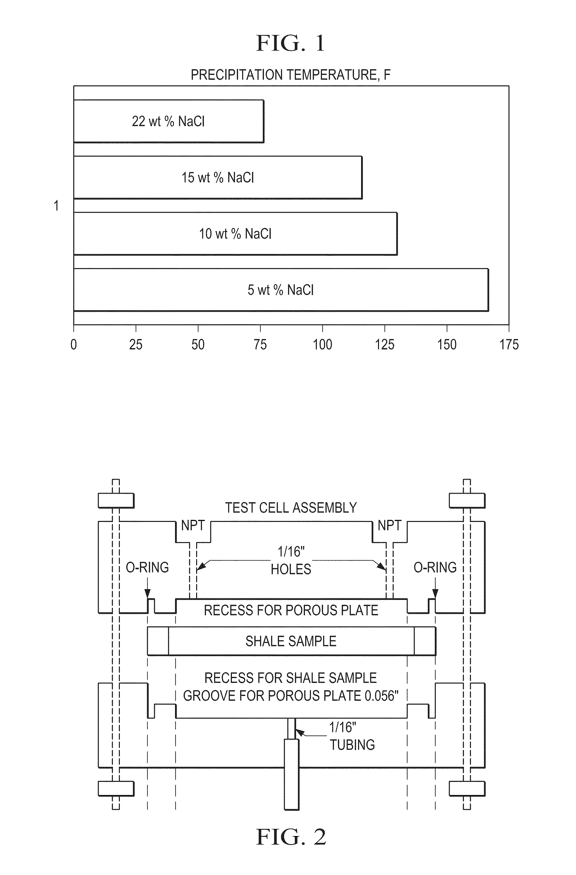
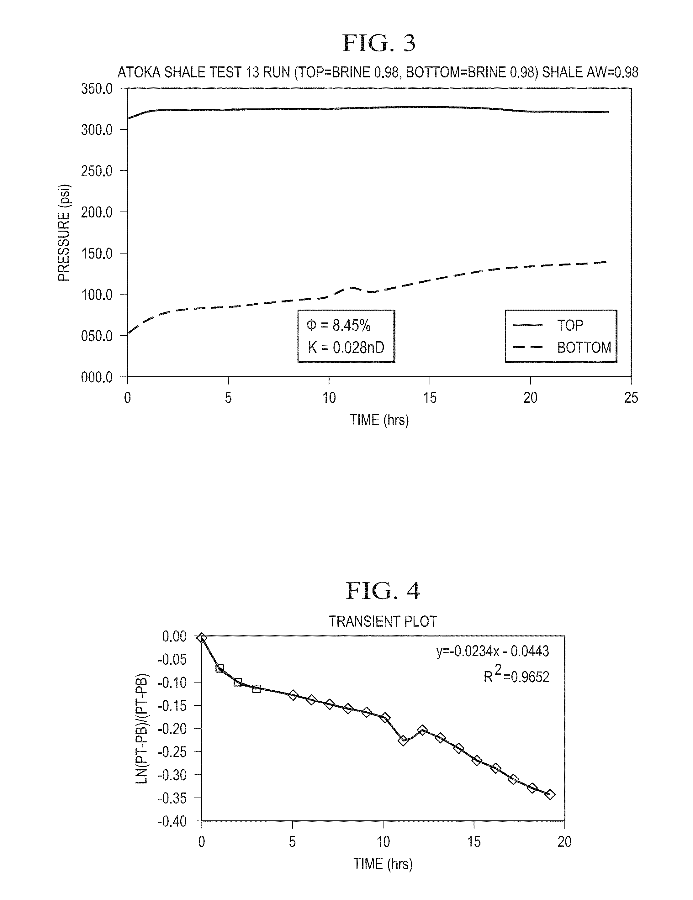
[0079]Using the test cell as depicted in FIG. 2, and using the samples of Atoka shale that had been equilibrated, two tests were run. In the next test (FIG. 6), a three-ste...
example 3
Nanoparticle Type and Size Tests
[0090]Tests were performed to investigate the effect of the Nyacol's 20 nm particles in contact with Atoka shale. This test was a straight application of 20 nm Nyacol's silica NP dispersion. In this test a sample of Atoka shale was exposed to a 40 wt %, 20 nm NP dispersion. Table 6 summarizes the test condition. As seen in FIG. 16, the bottom pressure built up in 17 hours at about 12 psi / hour, which is considered high. Nyacol's 20 nm particles did not plug the pores as well as 20 nm particles.
[0091]
TABLE 6Test Conditions using a 40 wt %, 20 nm NP dispersionShaleAtokaBrandNyacolTop FluidNPNP wt %41NP Size (nm)20Bottom FluidBrineAw top1Aw Bottom0.98Aw shale0.98
[0092]Next, tests were performed to investigate the effect of 5 nm particles in contact with Atoka shale (manufactured by Nyacol and 3M). The 3M and Nyacol 17 wt % and 15 wt %, 5 nm NP dispersions flowed across the surface of the Atoka shale sample. Test conditions are summarized in Table 7. As se...
example 4
Field Mud Tests
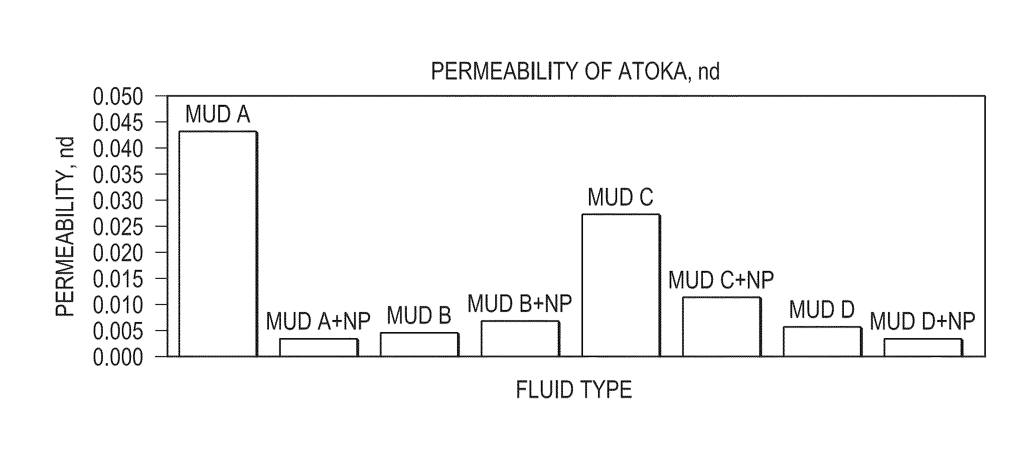
[0094]Field Muds in contact with Atoka shale. Tests were performed to observe the performance of Mud A. Table 8 gives the test conditions. The bottom pressure stabilized at 60 psi differential pressure in 25 hours. Using the transient method discussed hereinabove, the permeability of the sample was determined to be 0.044 nd. The pressure drop of 15 psi in the last 8 hours of this test may be the result of temporary temperature change in the laboratory.
[0095]
TABLE 8Field Muds in contact with Atoka shaleTop FluidMud ANP wt %0Bottom FluidBrineAw top1Aw Bottom0.98Aw shale0.98Top Pres. (Psi)290Bottom Pres. (Psi)50ResultStabilized at 60 psi differentialpressure in 25 hourswith a permeability of 0.044 nd.
[0096]
TABLE 9Field Mud Properties.Mud PropertiesMud AMud BMud CMud DDensity, lb / gal1211.69.39.8PV @ 80 F., cP18202811YP @ 80 F., lb / 100 ft2411369Solids Content, % by Volume19.518.518.511Water Content, % by Volume77797988Other Content, % by Volume3.52.52.51MBT, ppb Bentonite ...
PUM
| Property | Measurement | Unit |
|---|---|---|
| size | aaaaa | aaaaa |
| size | aaaaa | aaaaa |
| size | aaaaa | aaaaa |
Abstract
Description
Claims
Application Information
 - R&D
- Intellectual Property
- Life Sciences
- Materials
- Tech Scout
- Unparalleled Data Quality
- Higher Quality Content
- 60% Fewer Hallucinations
Browse by: Latest US Patents, China's latest patents, Technical Efficacy Thesaurus, Application Domain, Technology Topic, Popular Technical Reports.
© 2025 PatSnap. All rights reserved.Legal|Privacy policy|Modern Slavery Act Transparency Statement|Sitemap|About US| Contact US: help@patsnap.com


