
LED illumination device with isolated driving circuitry

a technology of led illumination and driving circuitry, which is applied in the direction of coupling device connection, lighting support device, lighting and heating apparatus, etc. it can solve the problems of not having long operating lifetime, requiring frequent replacement, and gas-filled tubes such as fluorescent or neon tubes, which may have longer lifetimes, etc., to achieve less stringent, improve the viability and energy performance of the device, and produce better diffuse heat

Active Publication Date: 2014-07-22
MAXLITE
View PDF25 Cites 10 Cited by
  • Summary
  • Abstract
  • Description
  • Claims
  • Application Information

AI Technical Summary

Benefits of technology

[0007]The present disclosure generally relates to several embodiments of a new illumination device using a plurality of LEDs, the illumination device is designed to better diffuse heat produced from a heating driver circuitry and the LEDs in a way that allows for either the operating or equilibrium temperatures of the heat sensitive elements as part of the device to be subject to less stringent temperature increases and therefore improve the viability and energy performance of the device. The new design includes toroid-shaped external rings for the plurality of LEDs and a middle opening for the driver circuitry. The new design further includes fins and the use of different spaces and openings within the housing to help control the flow of heat by way of thermal conduction, thermal convection, or thermal irradiation.

Problems solved by technology

Incandescent bulbs typically do not have long operating lifetimes and thus require frequent replacement.
Gas-filled tubes, such as fluorescent or neon tubes, may have longer lifetimes, but operating using dangerously high voltages, are relatively expensive and include hazardous materials such as mercury.
Further, both bulbs and gas-filled tubes consume substantial amounts of power.
Increasing the steady state temperature of the junction of an LED in turn reduces the efficiency and lifetime of the LED as the heated structure's resistivity is increased.
However, such increased brightness is accompanied by increased heat generation, lower lifetime of the structure generally resulting in a greater need to evacuate heat produced by the LED and other heat generating components to reduce its temperature and in turn increase life expectancy and reduce power consumption.

Method used


Image

  • LED illumination device with isolated driving circuitry
  • LED illumination device with isolated driving circuitry
  • LED illumination device with isolated driving circuitry

Examples


first embodiment

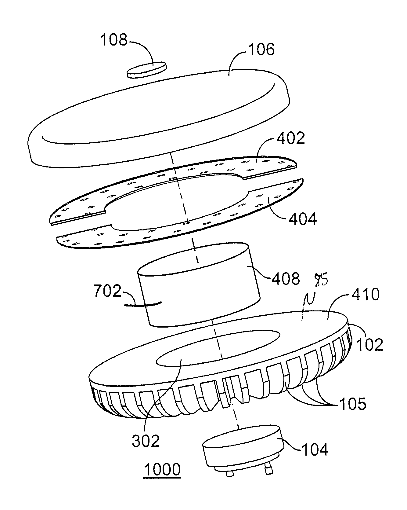
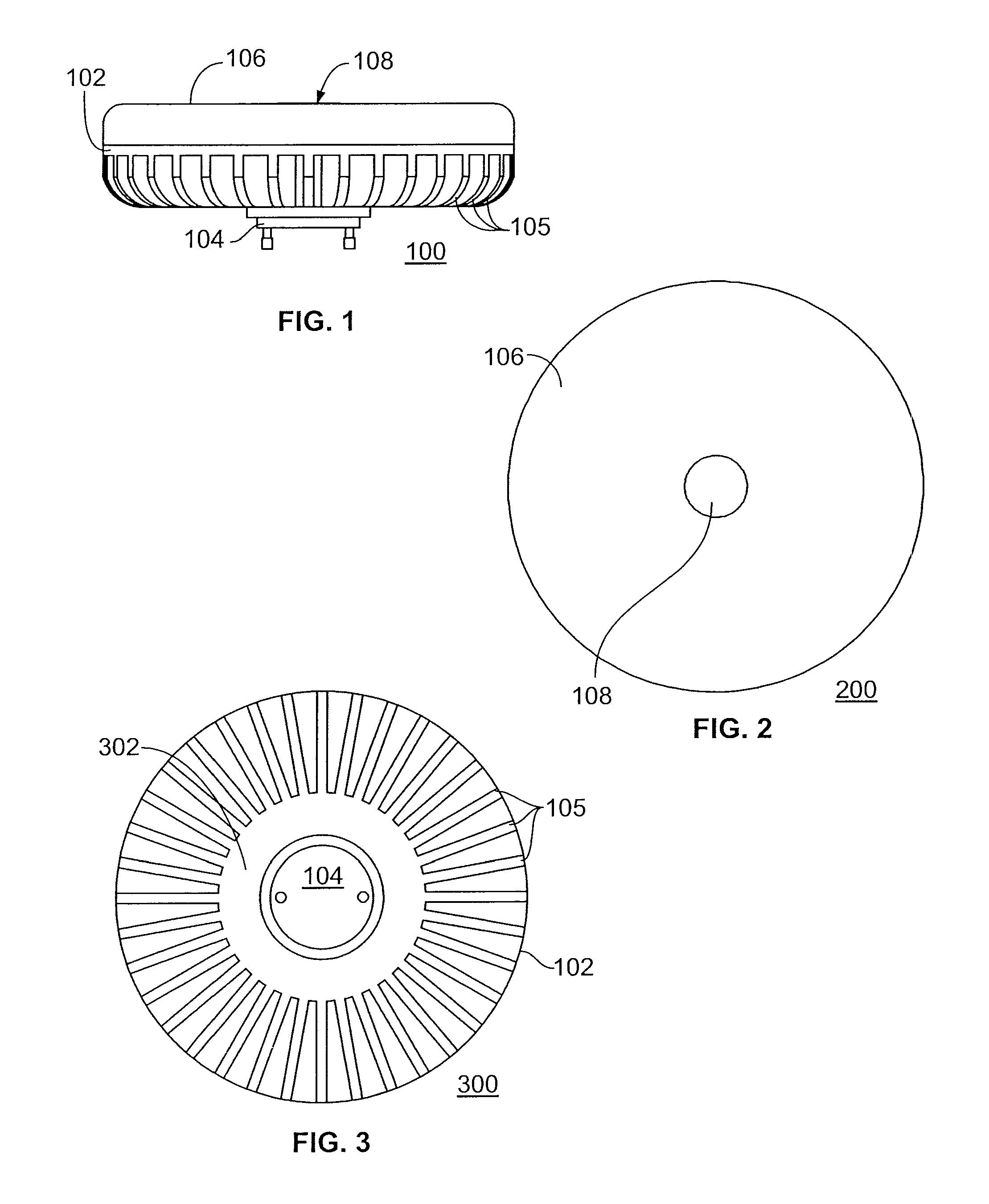
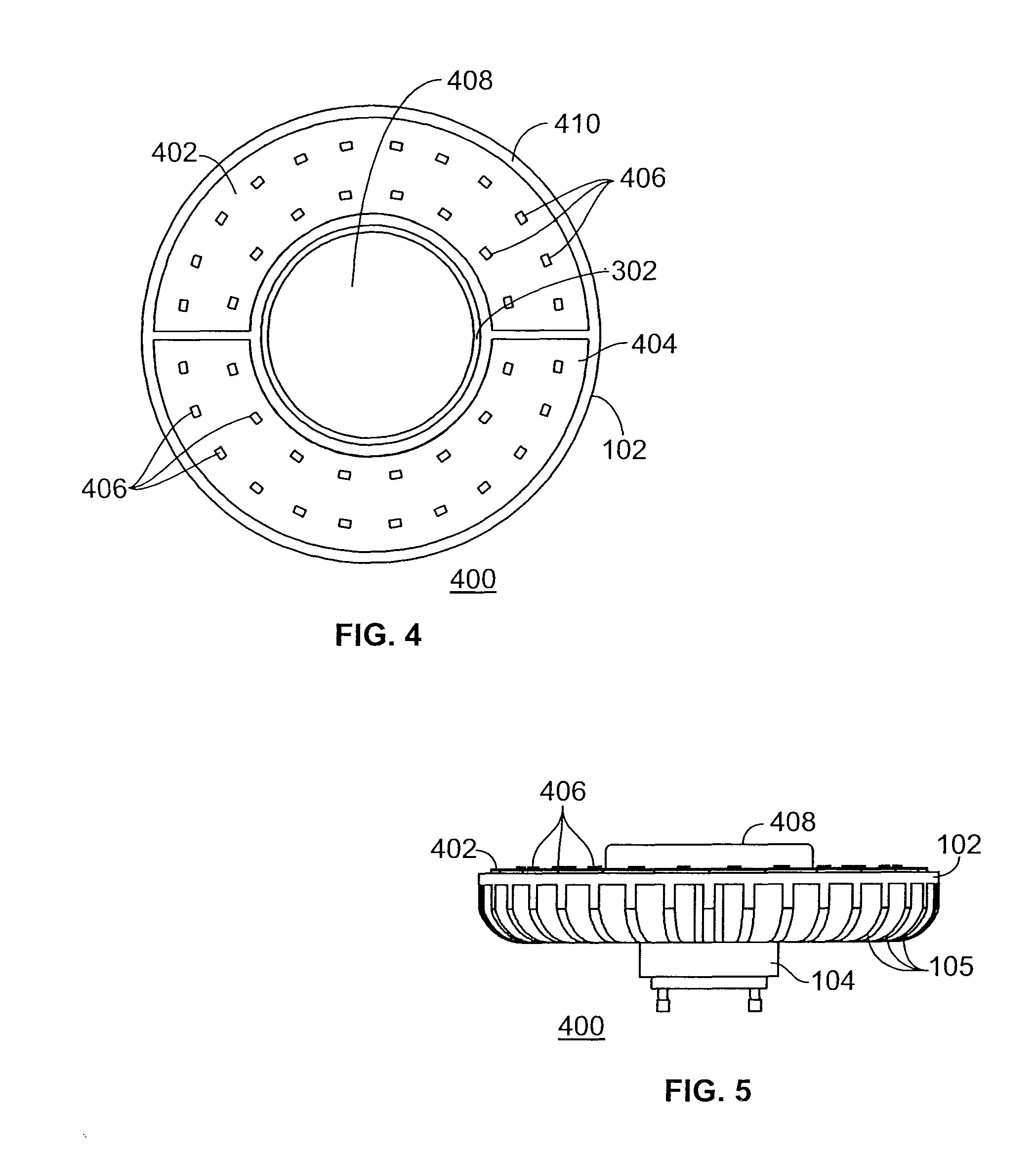
[0032]FIG. 1 illustrates a side view 100 of an LED illumination device in accordance with the disclosure. LED illumination device comprises housing 102 having a plurality of heat transfer fins 105, base plug 104, diffuser 106 and cap 108. In one embodiment, housing 102 comprises aluminum alloy 5052. In another embodiment, housing 102 comprises die cast aluminum. Those of skill in the art, however, will appreciate that any other form of metal or metal allow may be substituted for aluminum and / or aluminum alloy 5052 Those of skill in the art will further appreciate that different environments of use will dictate the type of metal or metal alloy used. To help evacuate heat, metal or metal allow is a good conductor and if given the right surface finish will have the required roughness to increase surface natural convection in the air. In one embodiment, as shown, housing 102 is generally circular in nature. It is recognized, however, that housing 102 may take any desired shape such as b...

second embodiment

[0053]FIG. 12 illustrates a side view 1200 of an LED illumination device in accordance with the disclosure. The LED illumination device of FIG. 12 includes a housing 1202, a diffuser 1206, a heat sink cap 1208, a plurality of housing fins 1210, a plurality of cap fins 1212 and a base plug 104. Housing 1202 is identical to housing 102 of FIG. 1 in construction but of a different shape. As described below, housing 1202 includes a housing trough for the plurality of LEDs 406. Housing 1202 includes a plurality of housing fins 1112 that are also identical to the plurality of fins 105 of FIG. 1 but adapted to fit the sides of housing 1202. The plurality of housing fins 1112 serve as heat sinks for the heat generated by the LED illumination device of FIG. 12. As before, base plug 104 may take the form of an GU-24, E-26 or E-26 adapter style base. Affixed to the top of the housing 1202 is diffuser 1206, which is also identical to diffuser 106 of FIG. 1 but of a different shape (as described...


PUM


Abstract

The present disclosure generally relates to several embodiments of a new illumination device using a plurality of LEDs, the device is designed to better diffuse heat produced from a heating driver circuitry and the LEDs in a way that allows for either the operating or equilibrium temperatures of the heat sensitive elements as part of the device to be subject to less stringent temperature increases and therefore improve the viability and energy performance of the device. The new design includes toroid-shaped external rings for the plurality of LEDs and a middle opening for the driver circuitry. The new design further includes fins and the use of different spaces and openings within the housing to help control the flow of heat by way of thermal conduction, thermal convection, or thermal irradiation.

Description

CROSS-REFERENCE TO RELATED APPLICATIONS[0001]This application claims the benefit of U.S. Provisional Application No. 61 / 523,695, filed Aug. 15, 2011.FIELD OF THE INVENTION[0002]The present disclosure generally relates to an illumination device and, more particularly, to a light emitting diode (“LED”)-based illumination device with improved heat evacuation propertiesBACKGROUND OF THE INVENTION[0003]Most lighting applications utilize incandescent or gas-filled bulbs, particularly lighting applications that require more than a low level of illumination. Incandescent bulbs typically do not have long operating lifetimes and thus require frequent replacement. Gas-filled tubes, such as fluorescent or neon tubes, may have longer lifetimes, but operating using dangerously high voltages, are relatively expensive and include hazardous materials such as mercury. Further, both bulbs and gas-filled tubes consume substantial amounts of power.[0004]In contrast, LEDs are relatively inexpensive, oper...

Claims


Application Information

Patent Timeline
Patent Type & Authority Patents(United States)
IPC IPC(8): F21V29/00F21V7/00
CPCF21V29/74F21Y2103/022F21V29/773F21Y2105/001F21V29/15F21V23/009F21Y2101/02F21V7/00F21V29/506F21K9/1355F21V29/00F21K9/13F21V3/049F21V15/01F21Y2105/10F21K9/23F21Y2115/10F21Y2103/33
Inventor STEEDLY, JAMES
Owner MAXLITE
Learn More