Transmission ratio variable device
a technology of transmission ratio and variable device, which is applied in the direction of oblique crank gearing, gearing, wobble plate gearing, etc., can solve the problems of preload applied to the deformation amount of the elastic member may vary, and the difficulty in maintaining the good meshing state of the nutation gear mechanism. , to achieve the effect of good meshing state of the nutation gear mechanism
- Summary
- Abstract
- Description
- Claims
- Application Information
AI Technical Summary
Benefits of technology
Problems solved by technology
Method used
Image
Examples
first embodiment
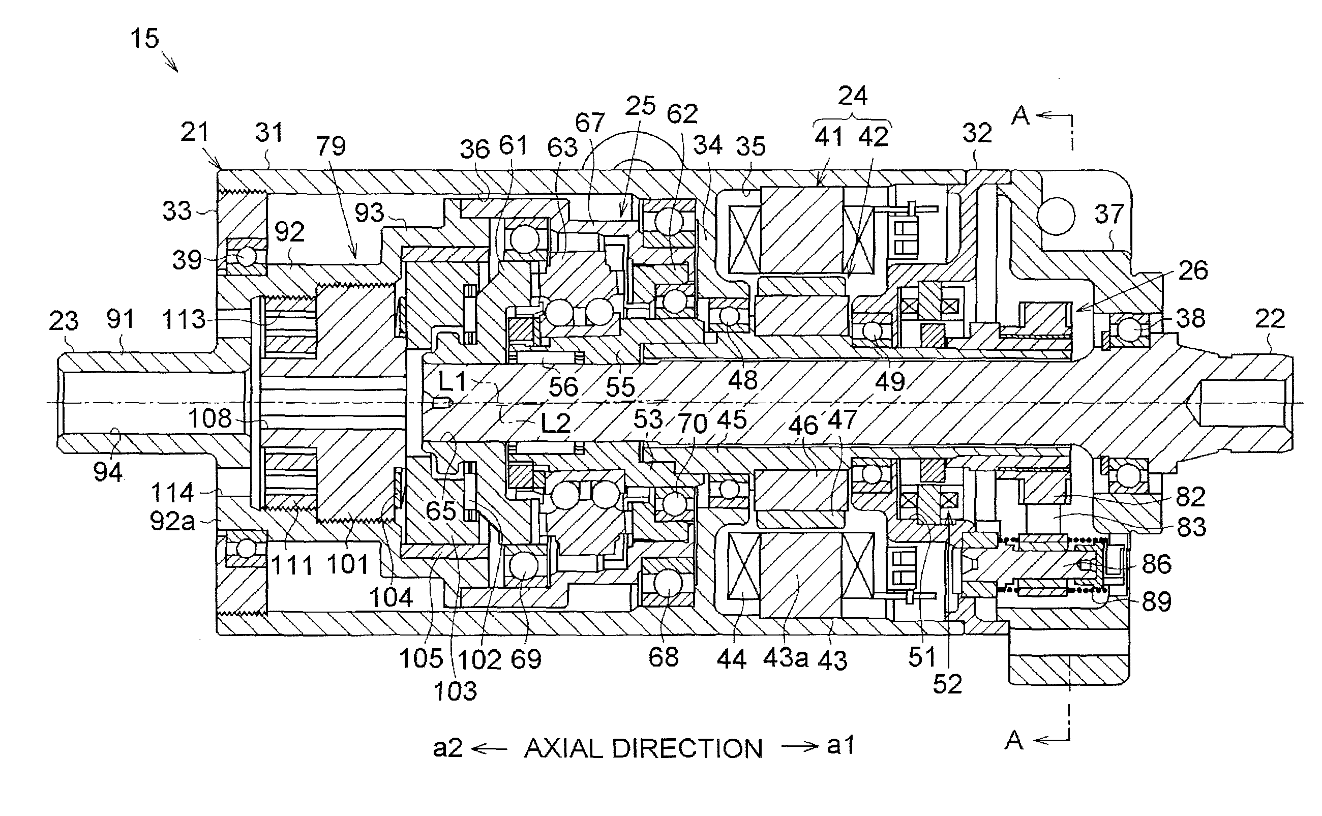
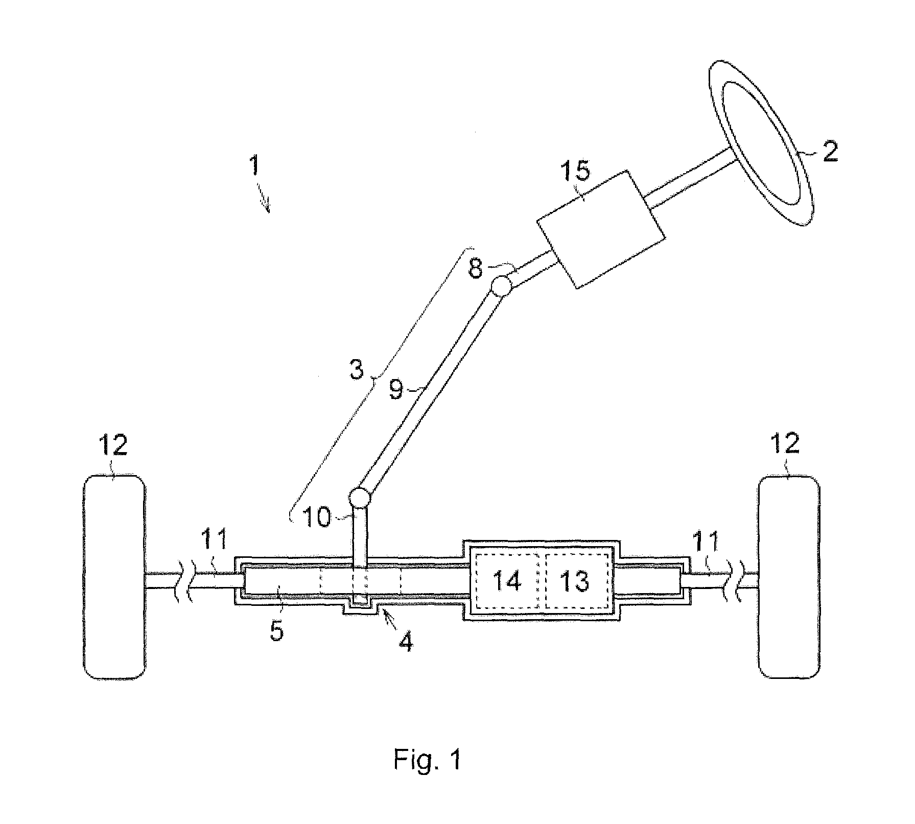
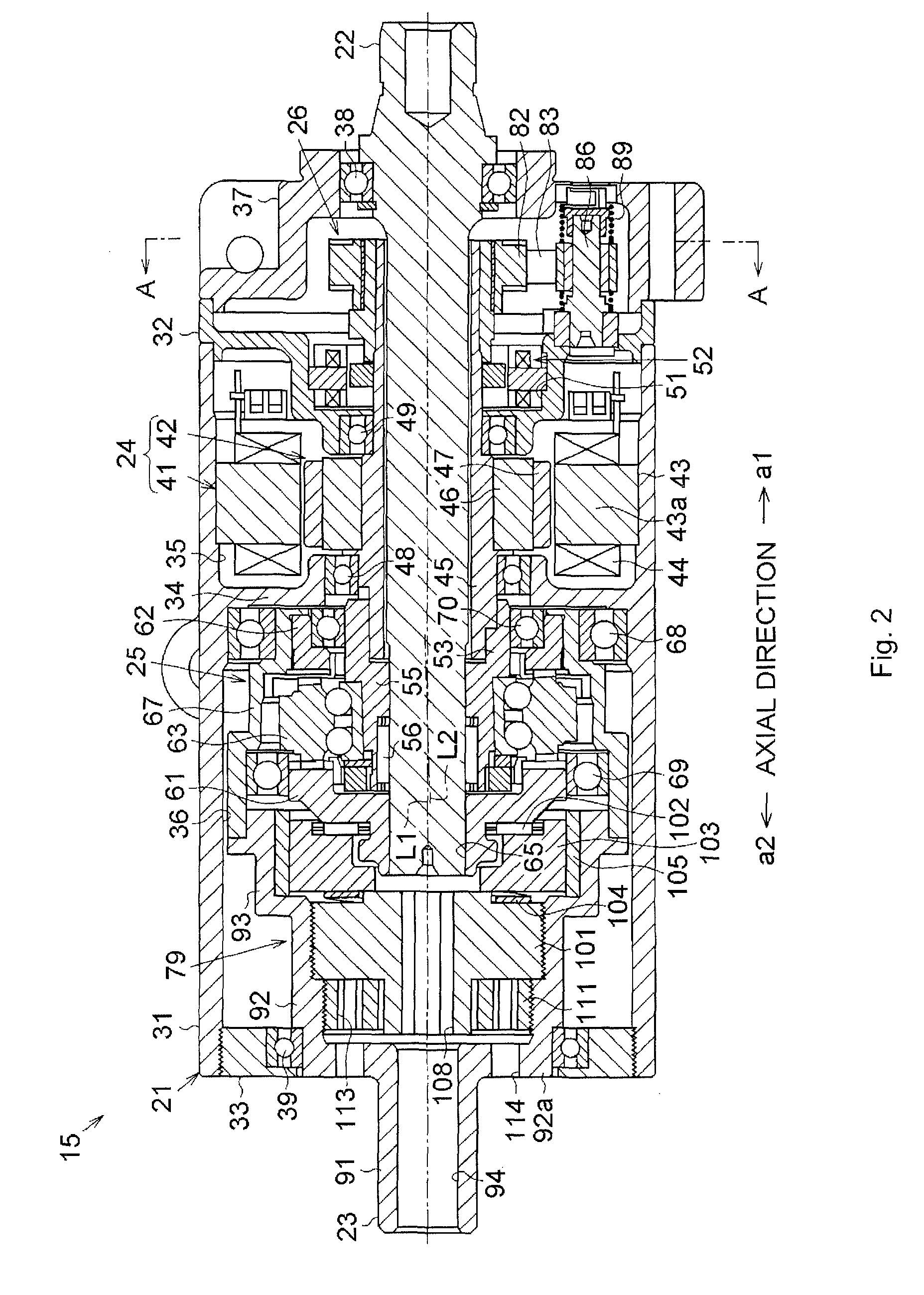
[0022]A first embodiment will be described with reference to the drawings. As shown in FIG. 1, in a vehicle steering system 1, a pinion (not shown) provided in a steering shaft 3 to which a steering wheel 2 is fixed meshes with a rack shaft 5 through a rack-and-pinion mechanism 4. Thus, rotation of the steering shaft 3 in association with a steering operation is converted into a linear reciprocating motion of the rack shaft 5 by the rack-and-pinion mechanism 4. The steering shaft 3 is formed by connecting a column shaft 8, an intermediate shaft 9, and a pinion shaft 10. A linear reciprocating motion of the rack shaft 5 in association with rotation of the steering shaft 3 is transmitted to knuckles (not shown) through tie rods 11 connected to respective ends of the rack shaft 5. Thus, a rudder angle of steered wheels 12, in other words, a traveling direction of a vehicle is changed. The vehicle steering system 1 according to this embodiment is configured as a so-called “rack assist t...
second embodiment
[0072]In the foregoing second embodiment, the soft member 133 is formed of a metallic material such as copper. However, the present invention is not limited to this, and the soft member 133 may be formed of another material such as resin or rubber as long as the soft member 133 has lower mechanical strength than mechanical strength of the preload adjusting plug 101. Alternatively, the soft member 133 may not be provided between the external thread portion 106 and the internal thread portion 95.
[0073]In the foregoing second embodiment, the elongated holes 131a and 131b are formed in the preload adjusting plug 101, and thus, the bridge portions 132a with low mechanical strength are formed on both sides of each elongated hole 131a in the longitudinal direction and the bridge portions 132b with low mechanical strength are formed on both sides of each elongated hole 131b in the longitudinal direction. However, the present invention is not limited to this, low-strength portions with low m...
third embodiment
[0075]In the foregoing third embodiment, knurling is used as the high μ process for increasing the friction coefficient μ performed on the contact surface 143a of the friction plate 143. However, the present invention is not limited to this, and other machining methods such as graining may be used. As the high μ process for increasing the friction coefficient μ, plating may be used to cover the contact surface 143a with a material having a high friction coefficient.
[0076]In the foregoing third embodiment, the high μ process for increasing the friction coefficient μ is performed on the contact surface 143a of the friction plate 143. However, the present invention is not limited to this, and the high μ process for increasing the friction coefficient μ may be performed only on a contact surface 101a (see FIG. 8) of the preload adjusting plug 101, which contacts the friction plate 143, or on both of the contact surfaces 101a and 143a. The high μ process for increasing the friction coeff...
PUM
 Abstract
Description
Claims
Application Information
 - R&D
- Intellectual Property
- Life Sciences
- Materials
- Tech Scout
- Unparalleled Data Quality
- Higher Quality Content
- 60% Fewer Hallucinations
Browse by: Latest US Patents, China's latest patents, Technical Efficacy Thesaurus, Application Domain, Technology Topic, Popular Technical Reports.
© 2025 PatSnap. All rights reserved.Legal|Privacy policy|Modern Slavery Act Transparency Statement|Sitemap|About US| Contact US: help@patsnap.com


