
Swimming pool cleaner with a rigid debris canister

a technology of debris canister and pool cleaner, which is applied in the direction of swimming pools, filtration separation, and separation processes, etc., can solve the problems of limiting the size of suction swimming pool cleaner, the opposite of suction cleaning cleaner, and the possibility of large debris clogging the pool pipe, so as to reduce the obstruction, improve buoyancy, and limit the entrapment of the cleaner

Active Publication Date: 2014-07-22
HAYWARD IND INC
View PDF348 Cites 36 Cited by
  • Summary
  • Abstract
  • Description
  • Claims
  • Application Information

AI Technical Summary

Benefits of technology

[0017]Another object of the invention is to provide an improved swimming pool cleaner which is able to successfully remove fine and large debris from the swimming-pool underwater surface.
[0039]In the inventive swimming pool cleaner, the cleaner body is adapted for securement of either a water-suction hose connected to a remote suction system or a venturi-line structure connected to a water-flow line fed by a remote pump such that the pool cleaner is interchangeably usable as a suction cleaner and as a pressure cleaner. A rigid debris-collection is canister secured to the cleaner body over the debris outlet to collect debris in the rigid canister and pass filtered water either back into the pool or to a remote suction system such that the collected debris remain at the pool-cleaner body for easy maintenance while allowing free flow of water through the rigid canister. The rigid canister is shaped to minimize obstructions to the pool cleaner movement in the pool by providing improved buoyancy and limiting entrapment of the cleaner by underwater pool structures such as ladders and the like.

Problems solved by technology

Suction swimming pool cleaners are also limited to the debris size due to loss of suction if the inlet and / or outlet orifices are widened to accommodate such large debris and of the possibility of large debris clogging the pool pipes.
With a pressure swimming pool cleaner, the limitation is the opposite to the suction cleaner.
The problem is that most often only one cleaner is used in a pool.
However, just few years later, when trees and bushes have grown up, the debris becomes overwhelming and constantly plugs the suction cleaner.
Although some swimming pool pressure cleaners have tails that supposedly whip the debris toward the main drain, in reality such tails only bring the dirt into suspension until it falls back on the pool bottom to start the process all over again.
Another common flaw of pool cleaners is the debris collector which typically presents certain maintenance difficulties.
This presents a hindrance to the movement of the cleaner and the hoses.
Moreover, such in-line debris collectors are typically located in awkward positions in the pool and are difficult to clean.
They also have a tendency to be caught under the cleaner wheels and be damaged.
These bags have to be replaced frequently due to tearing and other damage caused by manhandling and improper installation of the bag, including chemical damage to the material of the bag.
Furthermore, while flexible bags may trap some fine debris, most of slit and dirt flows back into the pool.
Flexible bags are hard to clean due to their collapsible nature.
Most often dirt gets logged into these closures making it difficult to clean the closures and the bag.
In the pool, flexible bags act like sails and are a hindrance to pool-cleaner movement.
When the bag is full of debris, the balance is lost and the bag falls over, may get caught under cleaner's wheels and obstructs free movement of the cleaner.
Once the bag falls over, cleaning ability of the cleaner is lost, but the cleaner may still attempt to move thereby damaging the bag and making it increasingly difficult to clean or replace the damaged bag.

Method used


Image

  • Swimming pool cleaner with a rigid debris canister
  • Swimming pool cleaner with a rigid debris canister
  • Swimming pool cleaner with a rigid debris canister

Examples


Embodiment Construction

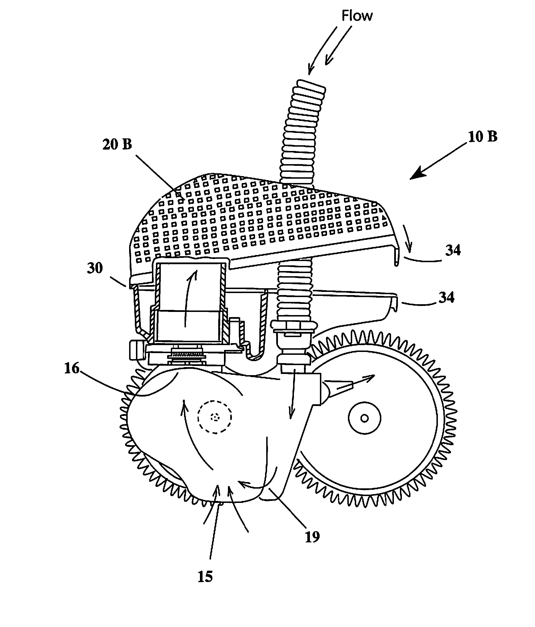
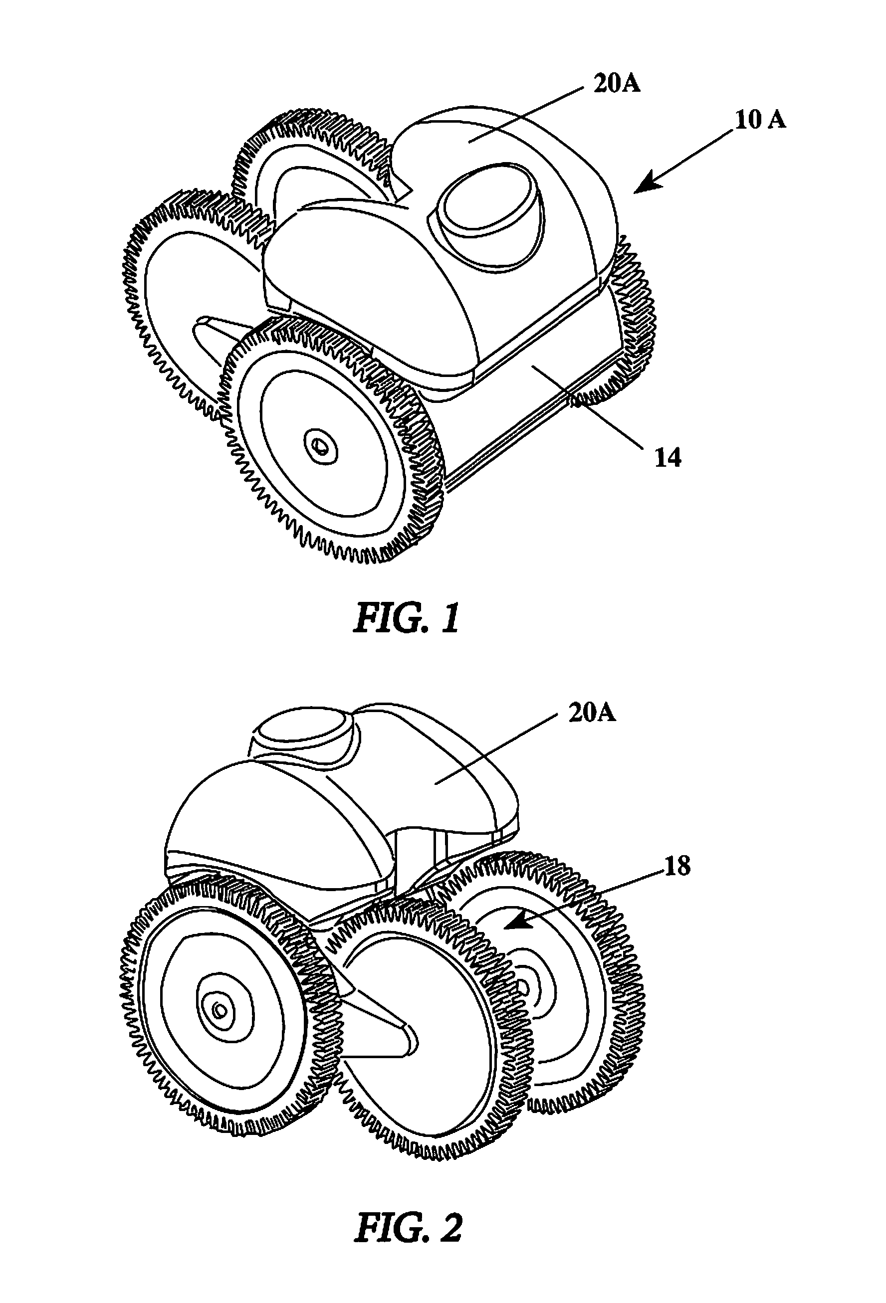
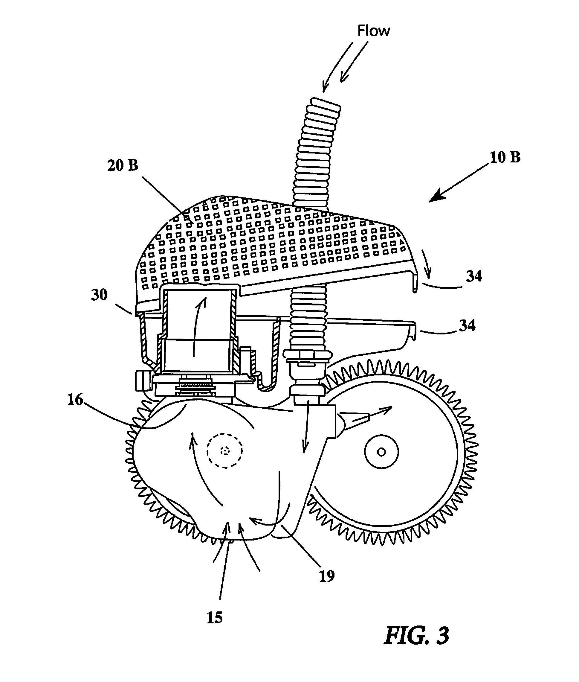
[0073]FIGS. 1-33 illustrate a preferred swimming pool cleaner 10 in accordance with the present invention. Swimming pool cleaner 10 is of the type movable along an underwater pool surface 11 to clean debris 12 therefrom. Swimming pool cleaner 10 includes a body 14 having a debris inlet 15 and a debris outlet 16. FIGS. 1-4 show preferred body 14 formed of two or more plastic pieces designed to accommodate the parts and features of the invention.

[0074]As best seen in FIGS. 1-3, swimming pool cleaner 10 includes a rigid debris-collection canister 20 secured to cleaner body 14 over debris outlet 16 to collect debris 12 in rigid canister 20 and pass filtered water 17 either back into the pool or to a remote suction system. In swimming pool cleaner 10, collected debris 12 remain at pool-cleaner body 14 for easy maintenance while allowing free flow of water through rigid canister 20. FIGS. 1-3 and 5-12 best illustrate that rigid canister 20 is shaped to minimize obstructions to movement of...


PUM

PropertyMeasurementUnit
solid structureaaaaaaaaaa
sizeaaaaaaaaaa
pressureaaaaaaaaaa

Abstract

A swimming pool cleaner of the type movable along an underwater pool surface to clean debris therefrom. The pool cleaner includes a body having a debris inlet and a debris outlet. A rigid debris-collection canister is secured to the body over the debris outlet to collect debris in the rigid canister and pass filtered water either back into the pool or to a remote suction system such that the collected debris remain at the pool-cleaner body for easy maintenance while allowing free flow of water through the rigid canister. The rigid canister is shaped to minimize obstructions to the pool cleaner movement in the pool by providing improved buoyancy and limiting entrapment of the cleaner by underwater pool structures. The cleaner body is adapted for securement of either a water-suction hose connected to a remote suction system or a venturi-line structure connected to a water-flow line fed by a remote pump such that the pool cleaner is interchangeably usable as a suction cleaner and as a pressure cleaner.

Description

FIELD OF THE INVENTION[0001]The present invention relates to swimming pool cleaners and, more particularly, to automatic swimming pool cleaners movable along an underwater pool surface for purposes of cleaning debris therefrom. Still more particularly, this invention relates to debris-collection means for swimming pool cleaners having the flow of water pumped and / or sucked by remote pumps into and through the pool cleaners.BACKGROUND OF THE INVENTION[0002]Automatic swimming pool cleaners of the type that move about the underwater surfaces of a swimming pool are driven by many different kinds of systems. A variety of different pool-cleaner devices in one way or another harness the flow of water, as it is drawn or pushed through the pool cleaner by the pumping action of a remote pump for debris collection purposes.[0003]Suction automatic pool cleaners are very successful when there is fine debris or debris that become soft in water. This fine debris is sucked up by the cleaner and dep...

Claims


Application Information

Patent Timeline
Patent Type & Authority Patents(United States)
IPC IPC(8): C02F103/42E04H4/16
CPCE04H4/1654C02F2103/42E04H4/1209
Inventor RIEF, MANUELARIEF, DIETER J.
Owner HAYWARD IND INC
Learn More