Inductively operated fluid dispensing device

a fluid dispensing device and inductive operation technology, applied in the direction of liquid/fluent solid measurement, container opening, container closing, etc., can solve the problems of inability to self-administer hypodermic injection, method is a source of discomfort, and cannot be easily detachable from the cartridge portion, etc., to achieve the effect of convenient detachable cartridge portion

Inactive Publication Date: 2014-07-29
ALPIMED
View PDF20 Cites 29 Cited by
  • Summary
  • Abstract
  • Description
  • Claims
  • Application Information

AI Technical Summary

Benefits of technology

[0016]Still another aim of the invention is to provide a device offering more precision in fluid delivery and that is simpler and easier to use than conventional injection devices.
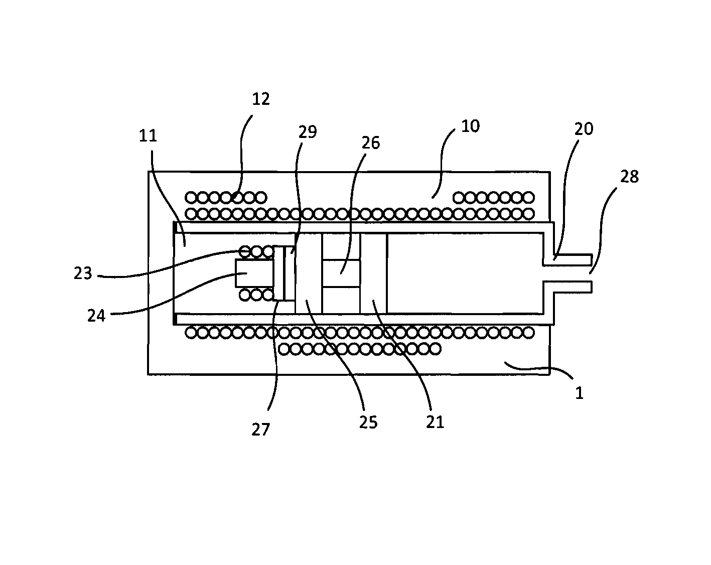
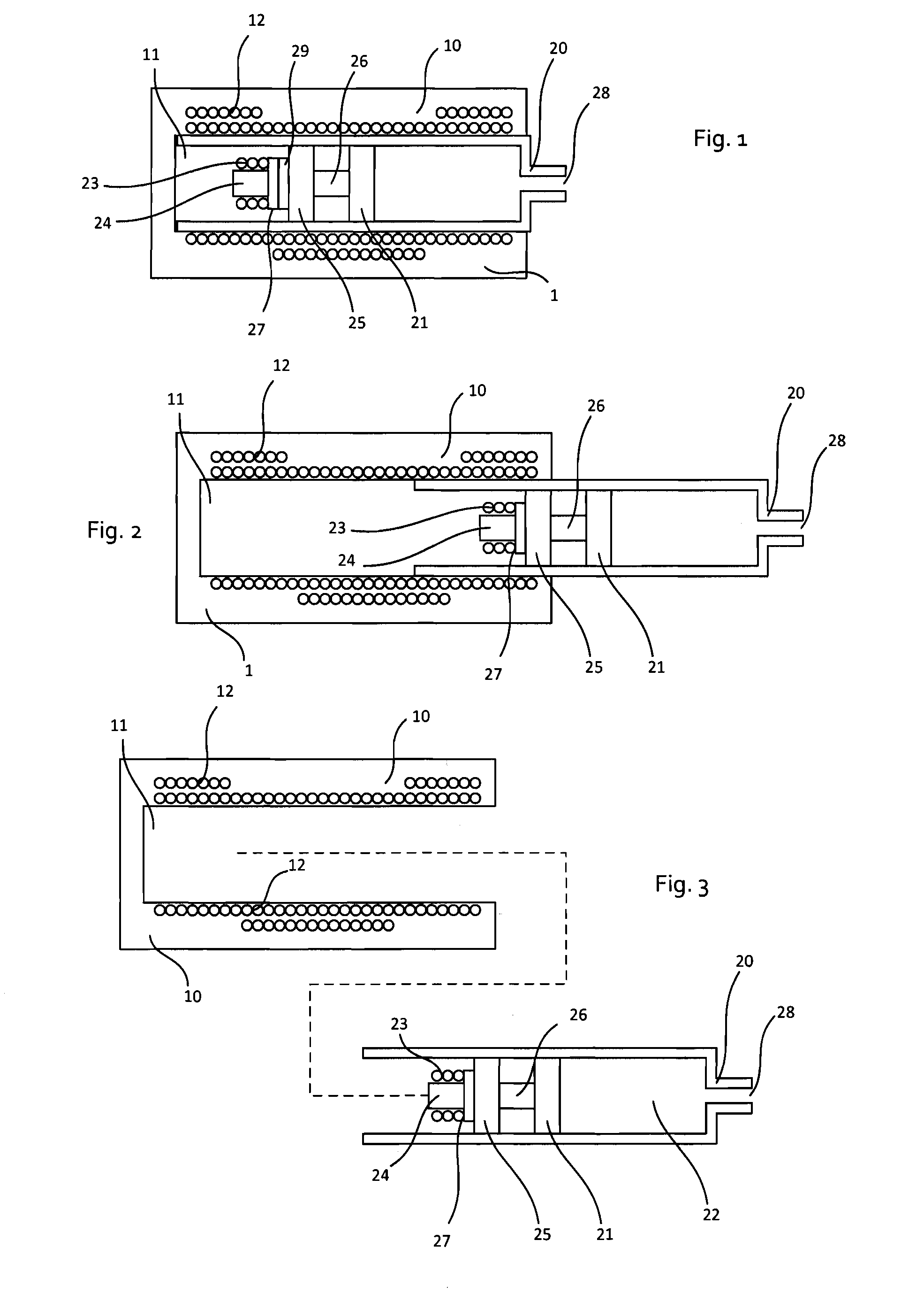
[0025]The device is advantageously provided with two main components, that is to say the outer casing and the inner cartridge. This enables an optimized use for each of these components as well as a quick and easy interchangeability of the cartridge. By placing the moving parts in the disposable cartridge, one removes the difficulty and the need of calibration and recalibration of the moving part after a given period. The outer casing contains no moving parts and therefore can be made extremely robust, miniaturized, at low cost.
[0026]Such an arrangement enables to spread the cost of the units over the period of usage and does not require a high investment at the beginning. This also substantially reduces the entry cost barrier for new users.
[0028]Except the sliding movement of the cartridge into the outer casing, there is no mechanical or electrical connection between the cartridge and the outer casing. The inductive coupling between the cartridge and the outer casing considerably simplifies the insertion and removal of the cartridge inside the casing.
[0033]The cartridge advantageously contains information that allows the protection of the user and prevents errors such as injection of a wrong medication or injection of a high concentration medication instead of a low concentration medication. In a further variant, involving more automated components, the outer casing dynamically and automatically adjusts its injection profile to the medication in the cartridge.

Problems solved by technology

Though effective, this method is a source of discomfort for patients requiring repeated injections over an extended period, for example diabetes patients.
Moreover a number of patients, in particularly elderly, visual-impaired, or patients suffering from arthritis, do not have the manual dexterity required to self-administer a hypodermic injection.
Unfortunately this is not always possible, even with the best injection technique.
These pens are easier to use than conventional syringes, yet they still require a certain amount of dexterity and force, and some patients find their use difficult.
Moreover, feedback about the proper operation of the system, about status, etc, is not provided.

Method used


Image

  • Inductively operated fluid dispensing device
  • Inductively operated fluid dispensing device

Examples


case 1

Coil to Inner Coil Power Transfer

[0060]The outer coil 12 inductively transfers power to the inner coil 23, which energizes the piezoelectric actuator 25. The coil assembly, provided with outer coil 12 and inner coil 23, provides a transformer allowing the required voltage increase to drive the piezoelectric elements. When the proper signal sequence on the outer coil is provided, a linear stepwise movement of the piezoelectric actuator is generated, thereby causing a linear stepwise movement of the plunger 21.

case 2

Coil to Inner Coil Actuation Commands Transmission

[0061]According to this embodiment, the cartridge includes an energy source 29, for example an electrochemical battery or an accumulator. External coil 12 is used to transmit inductively actuation commands to the actuator 25 through the inner coil 23. For example, the actuator could receive inductively commands to start or stop motion of the plunger at a given speed, or to advance or retract the plunger by a given number of steps, or by a given distance, according to the implementation. In a variant, the energy source may be a rechargeable accumulator or a capacitor that can be recharged inductively by coils 12 and 23, for example during the periods of inactivity of the device. For simplicity's sake the energy source 29 is represented in FIG. 1 only.

case 3

Coil—Outer Coil Bidirectional or Unidirectional Data Transfer

[0062]The PCB electronics 27 contains a data transfer circuit, such as RFID circuit, allowing data transfer to the outer coil 12. The cartridge data may be contained in specific data storage element or within the piezoelectric driving or controlling electronics 27. Data may be static non-erasable data written during manufacturing, such as the medication details, expiry date, concentration, maximum daily dosage, manufacturer data, exact injection volume at each step, and the like. The transferred data can also be related to the movement of the piezoelectric assembly such as the discharge and charge times of the piezoelectric elements. Such movement indication gives information about the smoothness of the movement, which can be used to detect any blockage in the fluid path or the eventual formation of bubbles.

[0063]The use of the outer coil assembly as a data transfer interface constitutes an independent aspect of the invent...


PUM


Abstract

A device for delivering fluid, having an elongated outer casing (10) provided with a substantially cylindrical inner chamber (11); an inner cartridge (20), for insertion into the inner chamber (11) and including a plunger (21) movable axially along a longitudinal axis A-A of an inner reservoir (22) towards an outlet (28). The device also includes a coil assembly (12, 23, 24) having an outer coil (12), an inner coil (23) and an inner coil core (24). The outer coil (12) is provided on the outer casing (10) and axially oriented along the chamber longitudinal axis. And, the inner coil (23) is provided in the inner cartridge (20) attached to the movable plunger (21).

Description

REFERENCE DATA[0001]The present application is a continuation of international patent application PCT / EP2010 / 054445 filed on 1 Apr. 2010, the entire contents of which is hereby incorporated by reference.FIELD OF THE INVENTION[0002]The present invention relates to a device for delivering fluid, comprising an elongated outer casing provided with a substantially cylindrical inner chamber, and an inner cartridge for insertion into said inner chamber. The cartridge comprises a plunger movable axially along a longitudinal axis of an inner reservoir towards an outlet. The device also comprises a coil assembly. The invention also relates to the corresponding method for delivering fluid from a cartridge.[0003]Some embodiments of the present invention relate to a device for administering pharmaceutical drugs by injection or infusion, yet the invention is not limited to this application and could also serve to deliver precisely metered amounts of adhesives, lubricants, solder pastes, chemical ...

Claims


Application Information

Patent Timeline
Patent Type & Authority Patents(United States)
IPC IPC(8): B65D88/54
CPCA61M5/14546
Inventor MORTAZAVI, BEHZAD
Owner ALPIMED
Why Eureka
Try Eureka