Solid-state drive with reduced power up time

a solid-state drive and power up time technology, applied in the direction of micro-instruction address formation, program control, instruments, etc., can solve problems such as memory access delays

Active Publication Date: 2014-07-29
WESTERN DIGITAL TECH INC
View PDF102 Cites 181 Cited by
  • Summary
  • Abstract
  • Description
  • Claims
  • Application Information

AI Technical Summary

Problems solved by technology

However, loading and updating the mapping table

Method used


Image

  • Solid-state drive with reduced power up time
  • Solid-state drive with reduced power up time
  • Solid-state drive with reduced power up time

Examples


Embodiment Construction

[0011]While certain embodiments of the inventions are described, these embodiments are presented by way of example only, and are not intended to limit the scope of the inventions. Indeed, the novel methods and systems described herein may be embodied in a variety of other forms. Furthermore, various omissions, substitutions and changes in the form of the methods and systems described herein may be made without departing from the spirit of the inventions.

DEFINITIONS

[0012]As used in this application, “non-volatile memory” typically refers to solid-state memory such as NAND flash. However, the systems and methods of this disclosure may also be useful in more conventional hard drives and hybrid drives including both solid-state and hard drive components. Solid-state memory may comprise a wide variety of technologies, such as flash integrated circuits, Chalcogenide RAM (C-RAM), Phase Change Memory (PC-RAM or PRAM), Programmable Metallization Cell RAM (PMC-RAM or PMCm), Ovonic Unified Mem...


PUM


Abstract

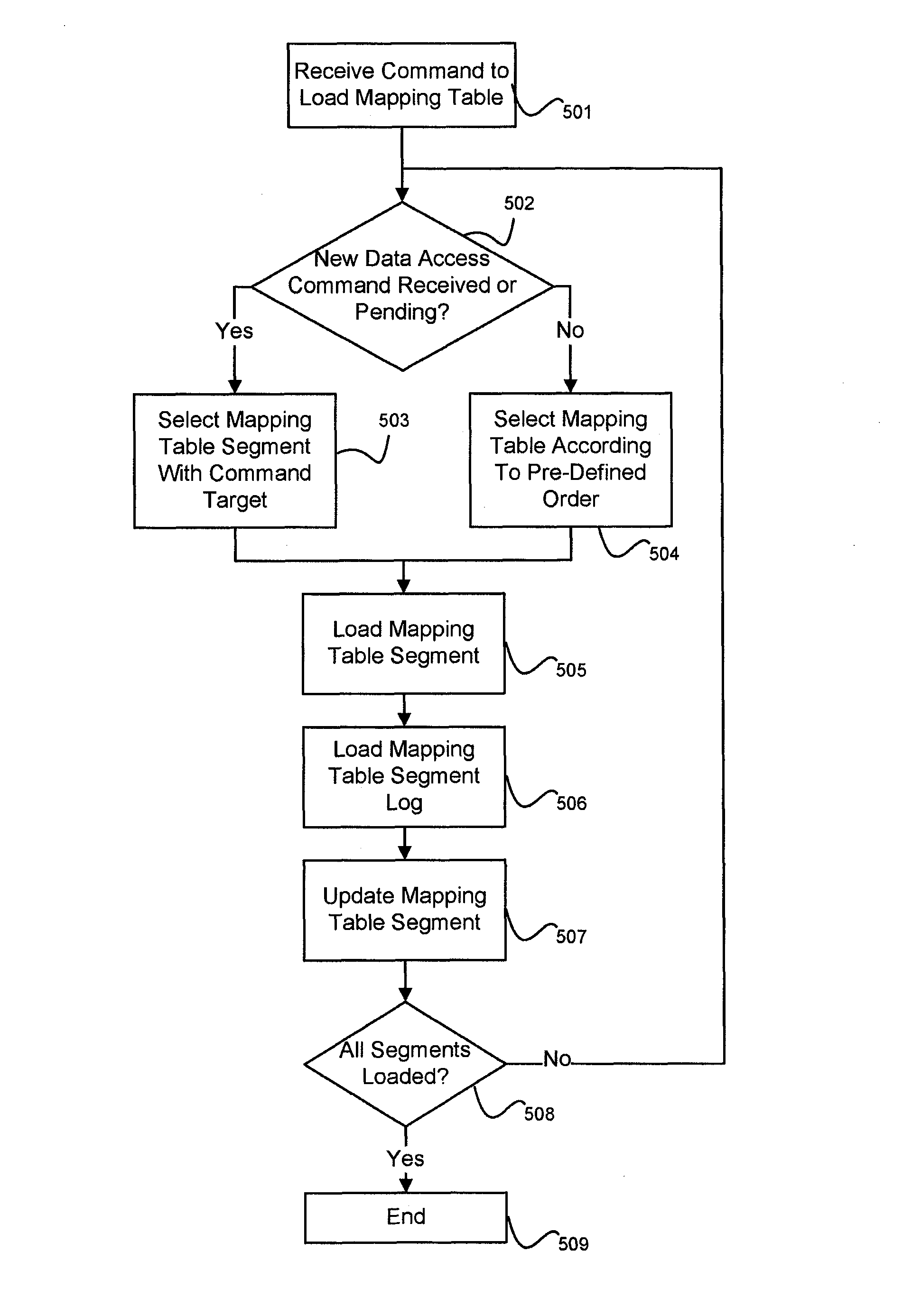
A non-volatile storage system is provided with reduced delays associated with loading and updating a logical-to-physical mapping table from non-volatile memory. The mapping table is stored in a plurality of segments, so that each segment can be loaded individually. The segmented mapping table allows memory access to logical addresses associated with the loaded segment when the segment is loaded, rather than delaying accesses until the entire mapping table is loaded. When loading mapping segments, segments can be loaded according to whether there is a pending command or by an order according to various algorithms.

Description

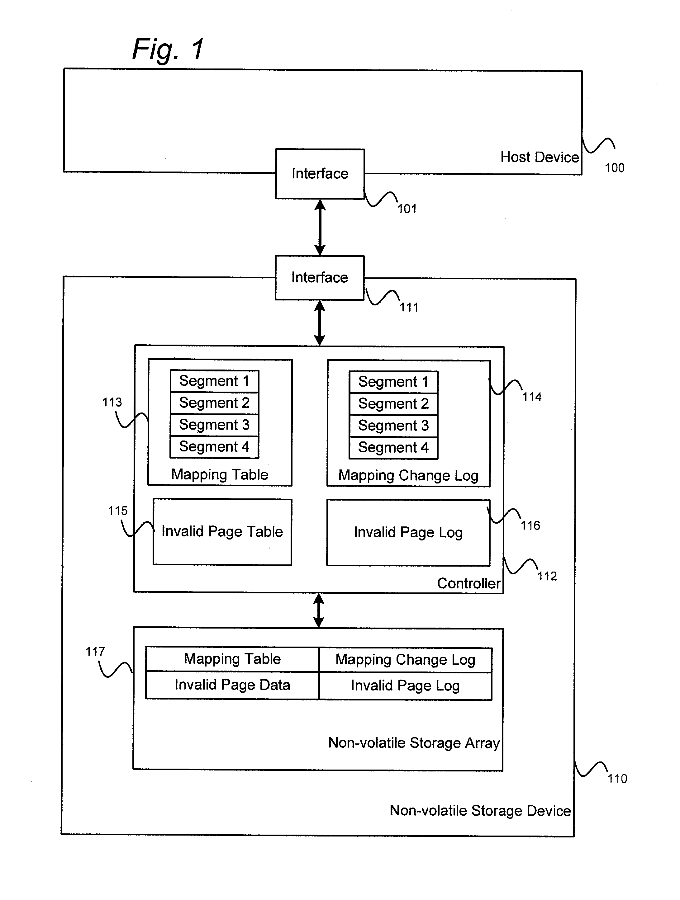
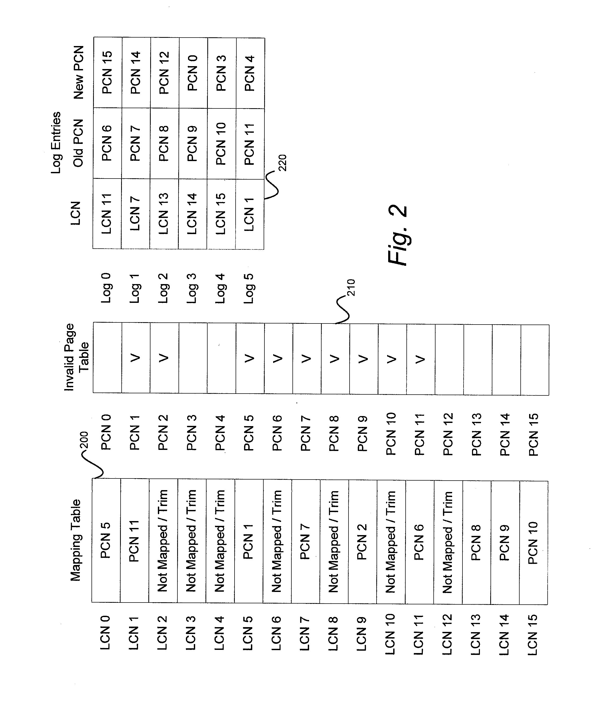
BACKGROUND[0001]1. Technical Field[0002]This disclosure relates to non-volatile storage subsystems, including but not limited to flash drives. More particularly, the disclosure relates to systems for reducing delays for an initial memory access associated with loading mapping data.[0003]2. Description of the Related Art[0004]Solid-state storage systems maintain a logical-to-physical mapping table for memory accesses. This mapping table associates logical addresses used by a host with corresponding physical storage locations in the non-volatile memory. On power up, the mapping table and a log of changes are loaded from non-volatile memory to reload the storage system status. However, loading and updating the mapping table from a log can incur delays for memory accesses.BRIEF DESCRIPTION OF THE DRAWINGS[0005]Systems and methods which embody the various features of the invention will now be described with reference to the following drawings, in which:[0006]FIG. 1 shows a non-volatile s...

Claims


Application Information

Patent Timeline
IPC IPC(8): G06F13/28G06F13/00G06F12/00
CPCG06F13/00G06F12/00G06F13/28G06F2212/7207G06F2212/7201Y02B60/1225Y02B60/1235Y02B60/1228G06F12/0246Y02D10/00
Inventor CALL, MATTHEWCHIU, LYNDON S.HORN, ROBERT L.PHAN, LAN D.
Owner WESTERN DIGITAL TECH INC
Why Eureka
Try Eureka