
Gas transport delay resolution for short etch recipes

a technology of gas transport delay and short process recipe, which is applied in the direction of diaphragm valves, engine diaphragms, water supply installations, etc., can solve the problems of gas delay delivery, adverse effect of short process recipe etch rate, and further enhanced

Active Publication Date: 2014-08-05
LAM RES CORP
View PDF27 Cites 14 Cited by
  • Summary
  • Abstract
  • Description
  • Claims
  • Application Information

AI Technical Summary

Benefits of technology

This solution effectively reduces gas transport delays, ensuring timely and efficient mixing of process gases, thereby improving etch rates and maintaining consistent dimensions on silicon wafers during short etch recipes.

Problems solved by technology

Transient gas flow delays to the process chamber, which are greater than the allowed gas settlement times, affect etch rates adversely for short process recipes (30 seconds to 60 seconds processes) due to non-stabilized or unsteady flows to the chamber.
The problem is further enhanced due to hardware differences in various gas boxes causing different transport delays to process chambers to create etch rate matching issues.
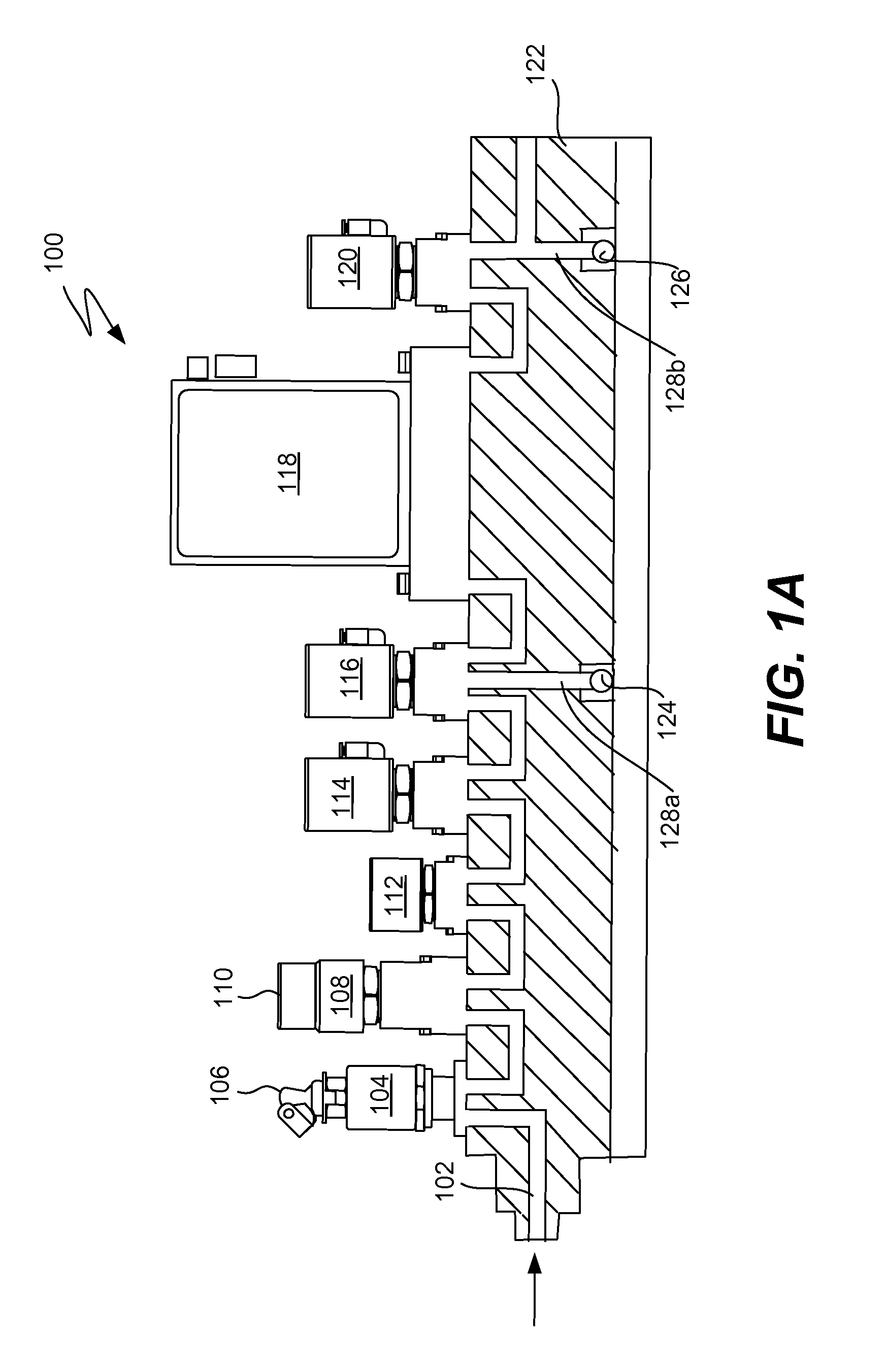
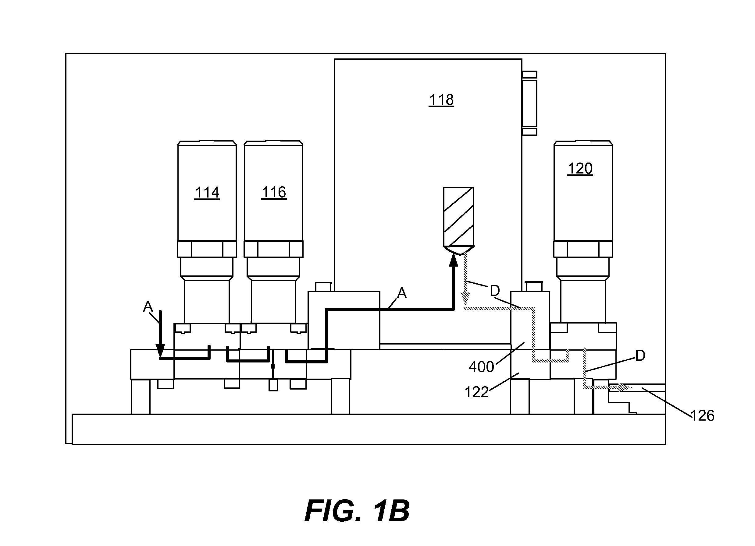
The gas delay delivery problems may be attributed to the volume through which low flow gases flow to mix with the higher flow carrier gas(es).

Method used


Image

  • Gas transport delay resolution for short etch recipes
  • Gas transport delay resolution for short etch recipes
  • Gas transport delay resolution for short etch recipes

Examples


example 1

[0042]The examples provided herein are merely for exemplary purposes and are not intended to be limiting. The current volume of a low flow gas from the MFC to the mixing manifold may be between about 4-5 cubic centimeters (cc), the pressure in the mixing manifold may be about 100 Torr, and Pambient may be 760 Torr. Thus, the delay time for a low flow gas to reach the mixing manifold (Tmm) may be calculated as follows:

[0043]φm=1⁢⁢sccm⁢⁢Pmm=100⁢⁢Torr⁢⁢Pambient=760⁢⁢Torr⁢⁢V=5⁢⁢cm⁢ / ⁢sec⁢⁢Tmm=5⁢⁢cm⁢ / ⁢second1⁢⁢sccm×100⁢⁢Torr760⁢⁢Torr=40⁢⁢seconds(4)

[0044]Thus, a 40 second delay in the flow of a gas to the mixing manifold would adversely affect etch rates for short process recipes that are 30 seconds to 60 seconds long, such as in reactive ion etching or gas modulated applications as the process gases may not be mixed properly or the process gases may not even be mixed together in the mixing manifold. Additionally, the slower the flow rate, the greater the delay will be. Thus, a way to redu...

example 2

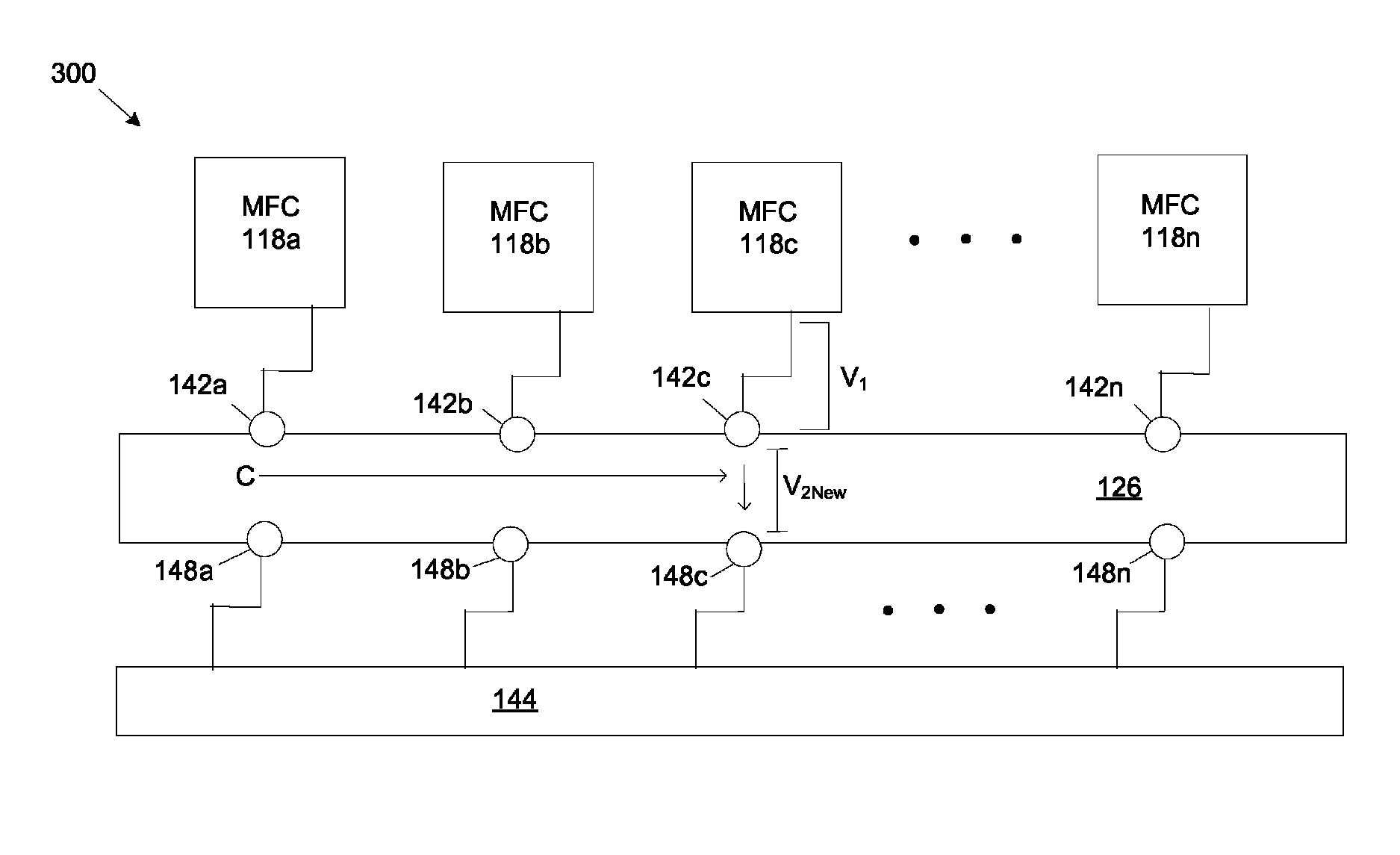
[0052]The following example is for exemplary purposes only and not intended to be limiting as any combination of gasses, flows, processes and the like may be used. In a first process the following requirement may be desired:

[0053]

MFC 118a:high flow gas AMFC 118bhigh flow gas BMFC 118clow flow gas C

Thus, mixing manifold exit (MME) 148a, b, n may be closed and MME 148c may be opened.

[0054]Any time thereafter, such as between about 20-60 seconds later, a second process may be desired. The second process may have the following requirements:

[0055]

MFC 118a:low flow gas AMFC 118bhigh flow gas BMFC 118chigh flow gas C

Thus, mixing manifold exit (MME) 148b, c, n may be closed and MME 148a may be opened. The MFCs and the MMEs may be automatically changed via a remote computer or controller.

[0056]After the second process is complete, such as between about 20-60 second, the user may desire to revert back to the first process and / or start a third process. As will now be known, any combination of ...


PUM

PropertyMeasurementUnit
volumeaaaaaaaaaa
pressureaaaaaaaaaa
pressureaaaaaaaaaa

Abstract

In one embodiment, an apparatus for providing a gas mixture of a plurality of gases, may have a plurality of mass flow controllers (MFCs), a mixing manifold in fluid connection with each plurality of MFCs, a plurality of mixing manifold exits positioned on the mixing manifold; and an isolation device in fluid connection with each of the plurality of mixing manifold exits.

Description

CROSS REFERENCE TO RELATED APPLICATIONS[0001]This application claims priority under 35 U.S.C. §119 (e) to U.S. Provisional Patent Application No. 61 / 016,908, filed on Dec. 27, 2007, entitled “Gas Transport Delay Resolution for Short Etch Recipes”, which is incorporated by reference herein for all purposes.FIELD OF THE INVENTION[0002]The present disclosure relates generally to gas delivery systems. More particularly, the present invention relates to a gas delivery system to reduce gas transport delays. Even more particularly, the present invention relates to a gas delivery system to reduce gas transport delays to efficiently mixing process gases.BACKGROUND OF THE INVENTION[0003]Process gasses are delivered from a gas box to a process chamber for various applications, such as reactive ion etching applications for building transistors on silicon wafers. Process gases are mixed downstream of the mass flow controllers (MFCs) to a mixing manifold prior to delivery to the process chamber, ...

Claims


Application Information

Patent Timeline
Patent Type & Authority Patents(United States)
IPC IPC(8): F16K11/10
CPCH01L21/67069Y10T137/877Y10T137/87885H01L21/67253Y10T137/0318F17D3/00F17D3/03H01L21/00
Inventor SHAREEF, IQBALTASKAR, MARKZEMLOCK, TONY
Owner LAM RES CORP
Learn More