Metal sheet container for transporting dangerous products

a metal sheet container and dangerous product technology, applied in the direction of containers, containers/bottles, containers, etc., can solve the problems of affecting the safety of the container, and reducing the service life of the container, so as to reduce the deformation and reduce the deformation. , the effect of reducing the deformation

Inactive Publication Date: 2014-08-12
BRASILATA S A EMBALAGENS METALICAS
View PDF37 Cites 4 Cited by
  • Summary
  • Abstract
  • Description
  • Claims
  • Application Information

AI Technical Summary

Benefits of technology

[0021]The present invention has as object to provide an improvement in the construction of a container in metal sheet, of the type which comprises a body formed by a tubular side wall having end edges to which upper and lower walls are peripherally affixed by double-seaming. The tubular body is provided with upper and lower circumferential end regions capable of deforming upon fall of the container in an inclined position at about 45°, absorbing the impact energy and preventing the loss of tightness of the double-seam and of the closure seat of the lid, if existing, without impairing the required stacking strength of said containers, even in situations in which the thickness of the metal sheet used for manufacture is reduced.SUMMARY OF THE INVENTION
[0025]With the construction defined above, it is formed a circumferential deformation region on the tubular side wall, close to at least one of the upper and lower double-seams and which is dimensioned to absorb, by a localized plastic deformation, the energy resulting from the impact of the filled container, which falls generally in an inclined position, with a rigid surface. The friezes which form each circumferential deformation region make the tubular side wall region, adjacent to the impact point, more easily deformable than the adjacent region of the upper wall, preserving the double-seam regions and the inner peripheral portion of the upper wall when the container is provided with an upper opening with a lid and dropped in an inclined and inverted position, allowing to minimize the deformations in the upper wall in the form of a ring or in a single-piece and, thus, maintaining the integrity of the lid closure and of the adjacent double-seam region.
[0026]The design and dimensioning of the friezes in each circumferential deformation region further allows obtaining, as a function of the inclined median leg and of the end legs orthogonal to the axis of the container, not only a controlled and sufficient absorption of the impact energy, but also an increased structural strength for the recipients upon stacking, also allowing, in certain cases, reducing the thickness of the metal sheet to be used in the formation of said containers.

Problems solved by technology

However, although said prior solutions guarantee an adequate retention of the lid on the closure seat in the pressure test conditions for dangerous products, they do not guarantee the integrity of the closure when the container, filled with the product, is submitted to a free fall, from a test height of usually 0.80 m to 1.5 m and against a rigid surface, with the lid turned downwards at an angle inclined at about 45°.
Said destructive deformation of the closure seat mostly results from the higher resistance to deformation by axial forces and from the lower resistance to deformation by radial forces to which the region of the side wall of the container, which is adjacent to the impact region, is submitted during the free fall test in the inclined position.
The problem regarding loss of tightness, caused by excessive deformation of the double-seam in the impact region, can occur both in the double-seam of the upper wall, when the container is allowed to fall in the inverted position, and in the double-seam of the lower wall, when the container is allowed to fall in the inclined but not inverted position.
It was also verified that the containers with a cylindrical or polygonal cross-section, generally square or rectangular, presenting a storage capacity of 1 gallon and of 9 and 5 liters, respectively, and having an upper wall in a single piece and optionally provided with a respective lid, are also vulnerable to the occurrence of loss of tightness by excessive deformation of the double-seam when submitted to impact caused by the container falling in an inclined position.
Although the problem regarding loss of tightness is more common in the region of the vertices when these define the impact region when the container falls, it can also occur in other rectilinear or bent double-seam parts, as in the case of the cylindrical containers.
Some of the known solutions, in order to minimize the problem related to the deformation of the closure seat and of the double-seam regions, when submitted to impact caused by the free fall of the fully loaded container and during test conditions, require the provision of auxiliary protecting devices aggregated to the container and which considerably raise the packaging cost.
Although constituting zones to be plastically deformable when the container falls in an inclined position, with the purpose of absorbing the impact energy and avoiding losing the tightness of the closure seat of the lid, if existing, and of the double-seam region submitted to deformation, this type of circumferential groove with the cross section in the form of a symmetrical V presents reduced capacity for absorbing deformation energy, requiring a higher number of grooves to absorb the deformation of the side wall and to avoid damages to the tightness of the container, but which impairs the capacity of the container to resist the stacking forces required by the current specifications.
Besides, the symmetrical V shape of the known grooves makes the tubular side wall of the container fragile to resist the compression forces, which impedes reducing the thickness of the metal sheet constitutive of the container body.
However, this rounded V-shape with a large opening angle impairs the plastic deformation of the groove sides to absorb the impact energy.

Method used


Image

  • Metal sheet container for transporting dangerous products
  • Metal sheet container for transporting dangerous products
  • Metal sheet container for transporting dangerous products

Examples


Embodiment Construction

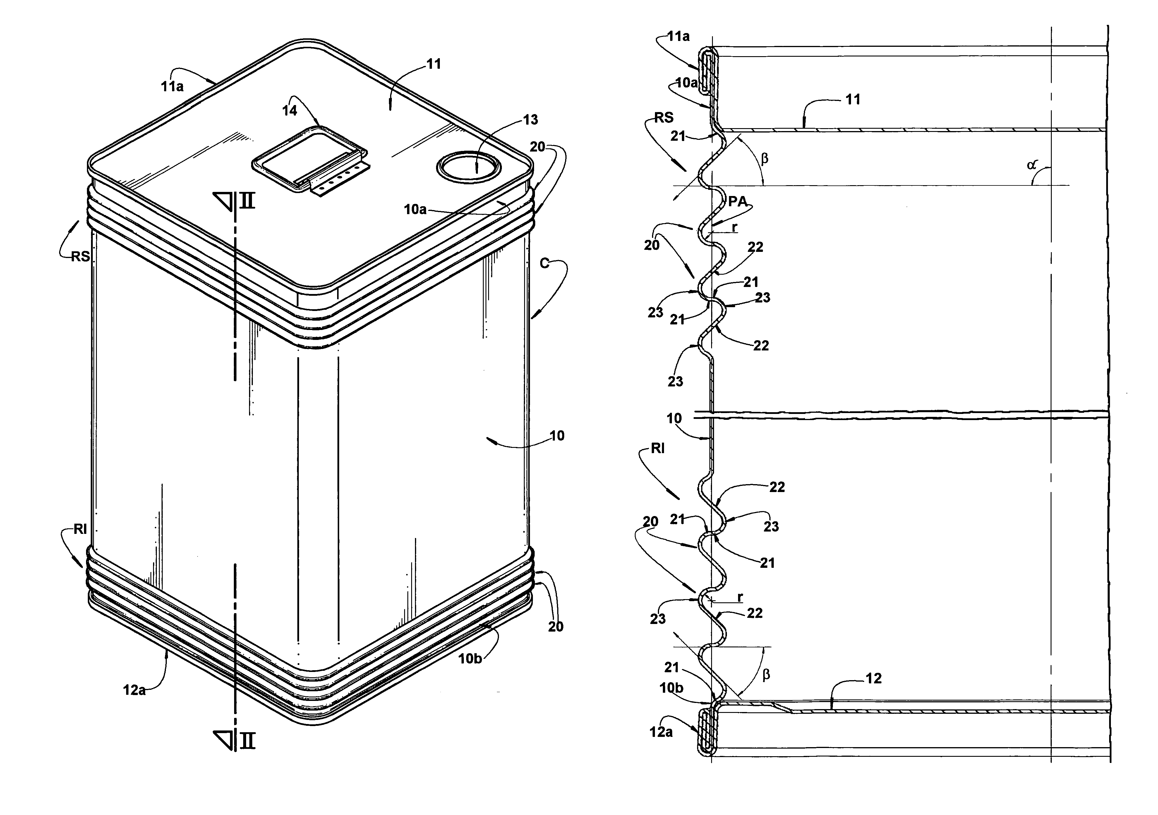
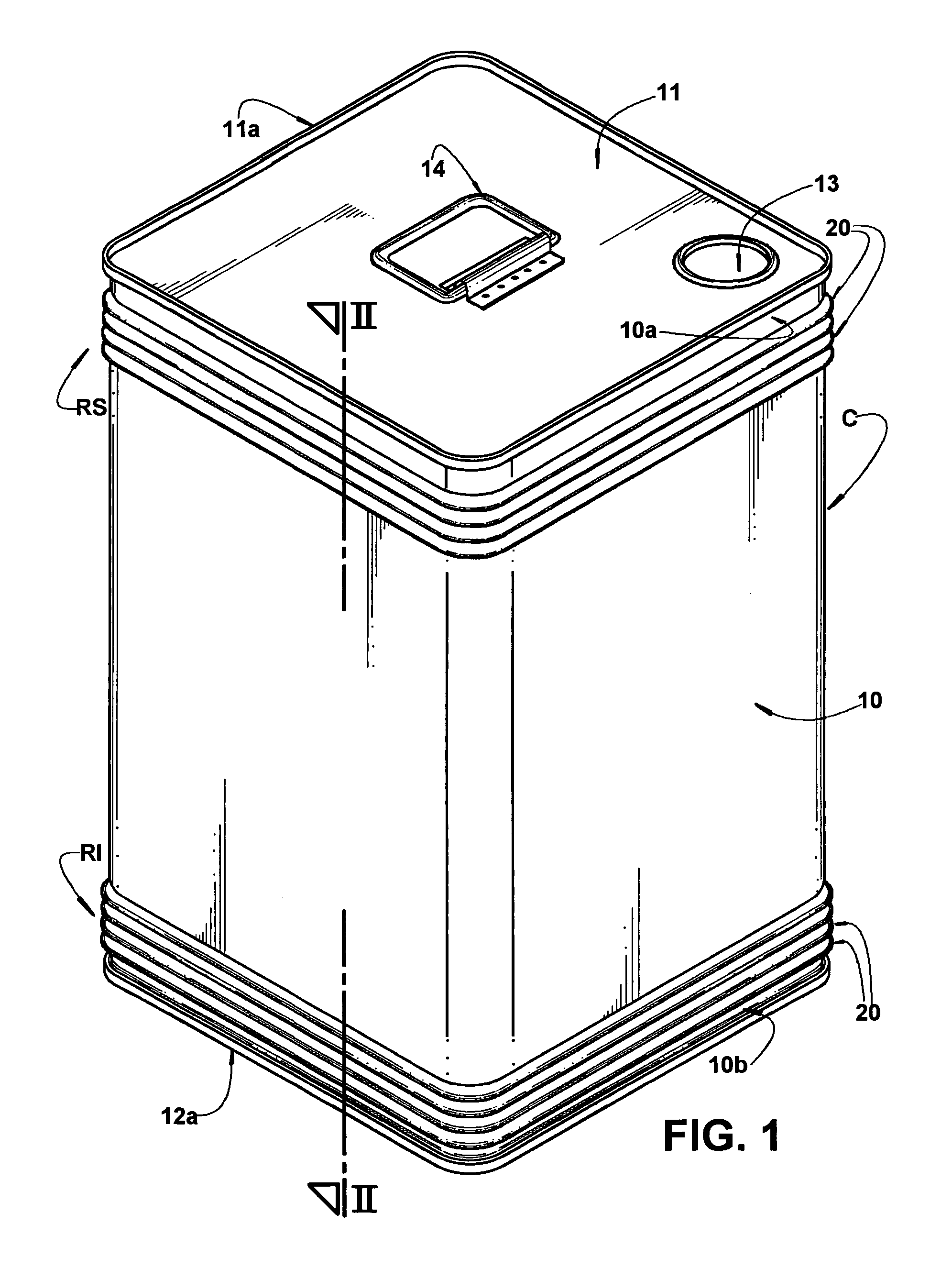
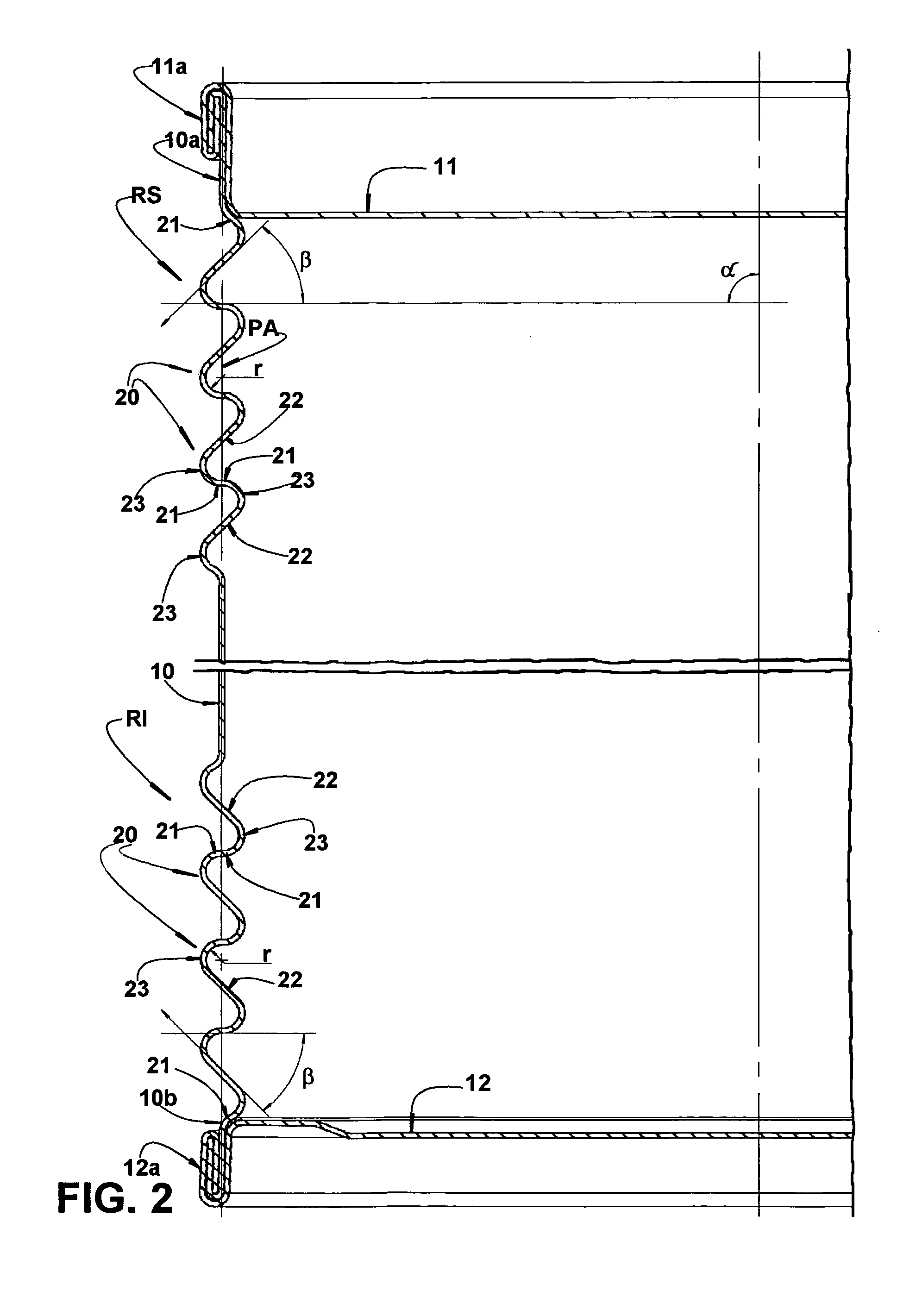
[0031]In the construction illustrated in figures from 1 to 3 of the enclosed drawings, the present container comprises a body C having a tubular side wall 10 with a square contour, and an upper wall 11 in a single piece sheet, whose outer peripheral portion is conventionally affixed, by a double-seam 11a, to an upper end edge 10a of the tubular side wall 10.

[0032]Although not illustrated herein, it should be understood that the upper wall 11 can be in the form of a structural ring, peripherally double seamed to the tubular side wall 10 and whose inner opening defines a seat onto which is seated and axially retained a lid which occupies a substantial extension of the area of said upper wall 11, as illustrated in FIGS. 1 to 6 of BR 0201566-8.

[0033]The illustrated container further comprises a lower wall 12 which is peripherally and conventionally affixed, by a double-seam 12a, to a lower end edge 10b of the tubular side wall 10.

[0034]In the illustrated construction, the upper wall 11 ...


PUM


Abstract

The container includes a body including a tubular side wall with upper and lower edges that are double-seamed to end walls. The tubular side wall includes a deformation region formed by circumferential friezes, which are parallel and adjacent to each other and have a Z-shaped profile with their end legs disposed in planes which define, with the axis of the tubular side wall, an angle between 45° and 90°. The end legs are interconnected by a median leg inclined in relation to the axis and defining, with the respective end legs, an angle not superior to 90°. The adjacent end legs of two consecutive friezes being coplanar and interconnected, by their opposite ends, to the respective median legs.

Description

FIELD OF THE INVENTION[0001]The present invention refers to an improvement applied to a container in metal sheet, such as a can, pail or other metallic container of the type which comprises a side wall which is cylindrical or has a polygonal contour, generally square or rectangular, to whose end edges are double seamed a bottom wall and an upper wall, which can be annular, with a large discharge opening closed by a press-fit lid or by a single-piece lid provided with a small discharge opening. The invention allows the present can to be used for containing dangerous products in volumes of about 1 to 20 liters.BACKGROUND OF THE INVENTION[0002]It is known in the prior art the construction of containers in metal sheet, such as cans and pails, in which the side wall presents a square, rectangular or cylindrical contour, and the upper wall is provided in a single piece or in the form of a substantially circular large opening defined internally to a closure seat formed on the upper wall, t...

Claims


Application Information

Patent Timeline
Patent Type & Authority Patents(United States)
IPC IPC(8): B65D1/44B65D6/38B65D8/12
CPCB65D7/46B21D51/2661B65D5/748B65D7/045
Inventor ALVARES, ANTONIO CARLOS TEIXEIRACUNHA, SILVERIO CANDIDO DA
Owner BRASILATA S A EMBALAGENS METALICAS
Why Eureka
Try Eureka