
Method for the production of a refractory filter

Active Publication Date: 2014-08-12
FOSECO INT LTD
View PDF12 Cites 6 Cited by
  • Summary
  • Abstract
  • Description
  • Claims
  • Application Information

AI Technical Summary

Benefits of technology

The present invention provides an improved method for making foam filters and filters made using this method. The method and filters offer advantages such as improved efficiency, reduced cost, and improved performance.

Problems solved by technology

Molten metals usually contain solids such as oxides of the metal and other impurities which may cause the final cast product to have undesirable characteristics.
Although they are robust and easy to handle, their filtration efficiency is relatively poor because the molten metal only travels a short and straight path through the filter.
Although the filtration efficiency is much improved over the previously described cellular filters, ceramic foam filters are mechanically weaker (the strands, particularly at the edge of the filter are prone to breakage).
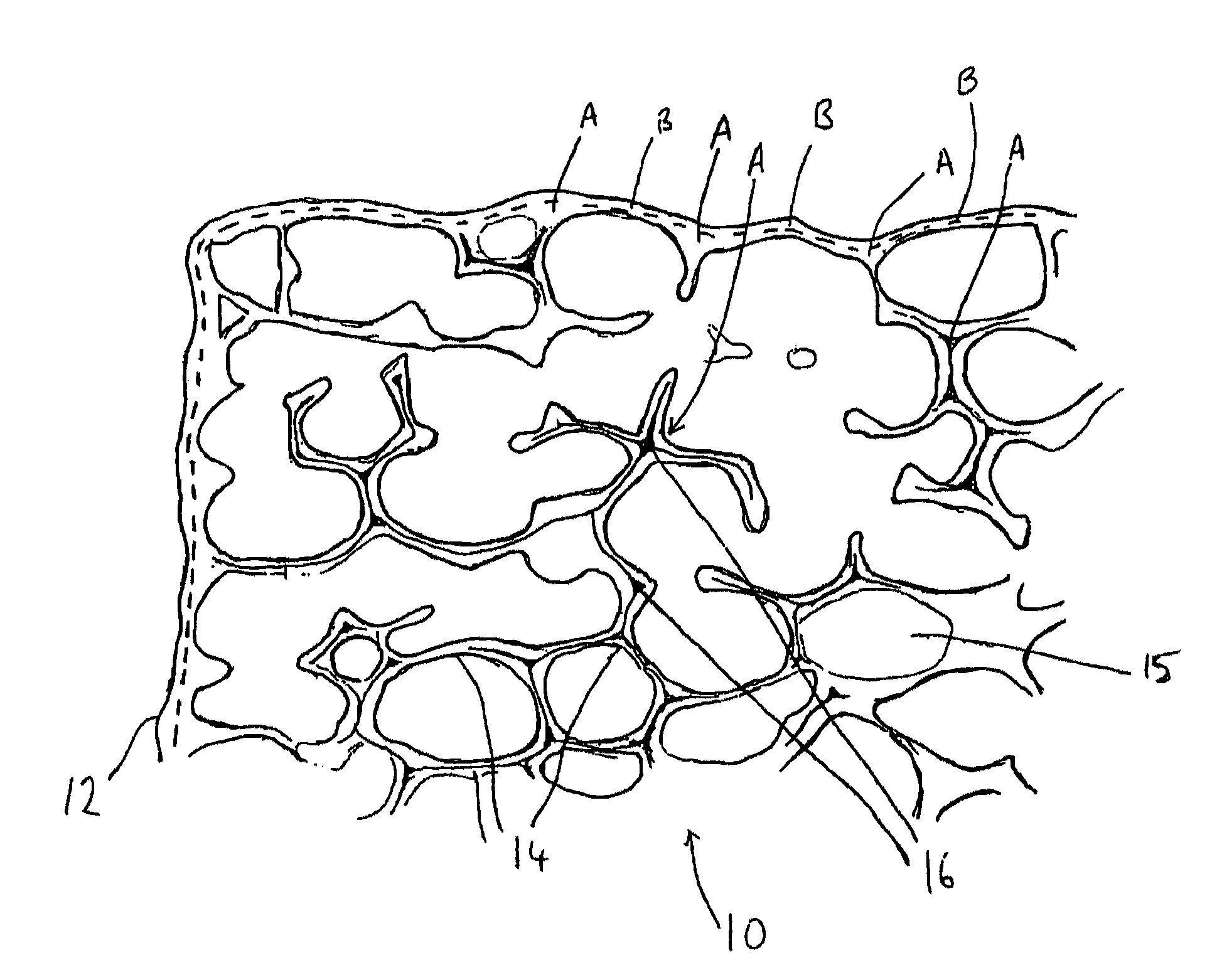
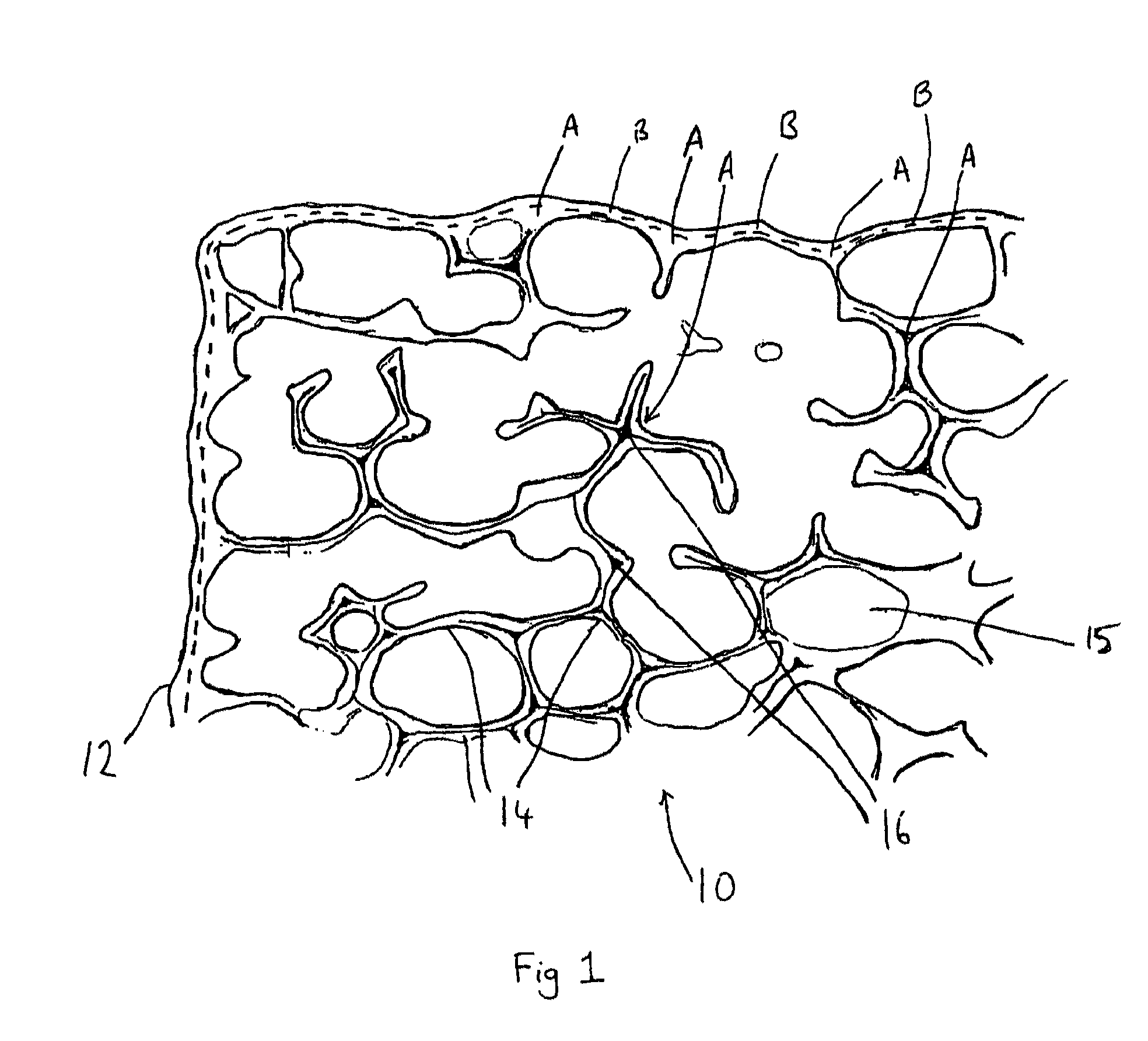
Since the foam filters are porous in all directions and the edge surfaces are uneven, it is possible for some molten metal to flow around the edges of the filter or only pass through part of the filter, thereby reducing filtration efficiency.
This problem is exacerbated if strand breakage has occurred during transport of the filter or during positioning of the filter in the refractory wall (it will be noted that the broken strands themselves can contribute to the impurities in the final casting).
Increasing the amount of slurry used to impregnate, i.e. coat the foam, in the production of the filter increases its strength but also results in reduced filtration efficiency due to the higher weight and reduced porosity.
In addition, temperature losses in the metal will increase metal viscosity hence filters with a high heat capacity will cause increased thermal losses and reduce priming.
A heavier filter in which the coated strands are thicker is therefore undesirable since it will have a greater heat capacity.
This is disadvantageous from both an economic and environmental standpoint as it increases the amount of energy required to heat the metal to the required temperature.
In addition to the extra weight, filters produced using an increased amount of slurry will have reduced metal flow rates due to the increased strand thickness and smaller pores, and will have a greater tendency to block.
Reduced flow rates and premature blockage can have adverse effects on metal casting, for example, by increasing pouring times or causing incomplete mould filling, and it may be necessary to increase the size of the filter or to increase the pore size of the foam.
Increasing the level of slurry is therefore not a practical solution to increasing the strength of foam filters, particularly the edges of foam filters.
In both embodiments, the resulting coating is thick thereby reducing the useful volume of the filter and also increasing its heat capacity.

Method used


Image

  • Method for the production of a refractory filter
  • Method for the production of a refractory filter
  • Method for the production of a refractory filter

Examples


example 1

Silicon Carbide Foam Filter with a Closed Edge Coating

[0087]A closed edge filter having the dimensions 50 mm×50 mm×22 mm was prepared from a 10 ppi reticulated polyurethane foam piece having the appropriate dimensions (as described above). The application rate of slurry was reduced as compared to Comparative Example 1.

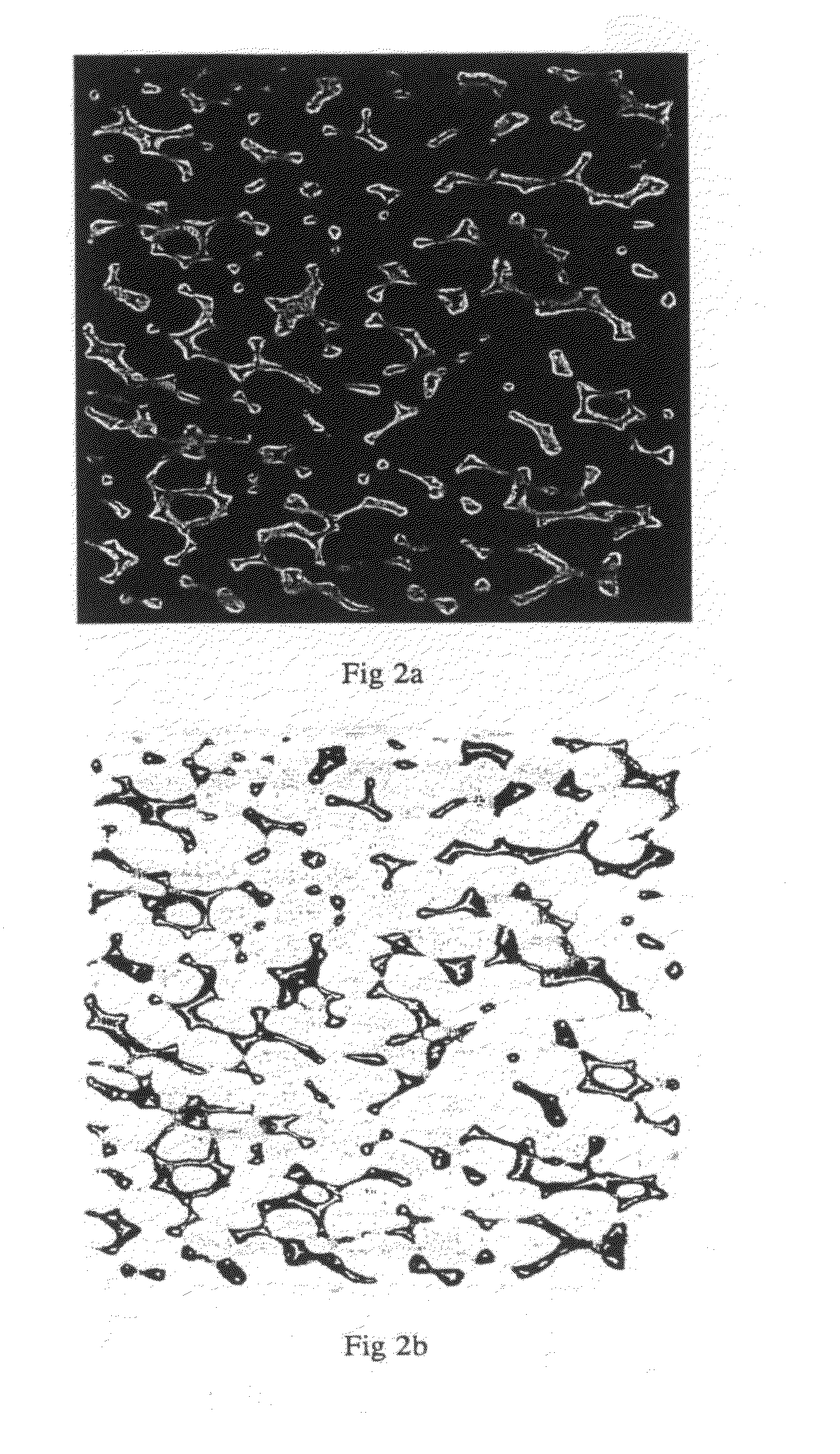
[0088]FIG. 3a is a cross-section of the entire filter of Example 1 which has dimensions 50 mm×5 mm×22 mm. The irregular network of strands of refractory material can be seen clearly together with the continuous closed edge. The closed edge filter is seen as the light regions and the pores / voids as the dark areas. The coating and the strands have a similar thickness, i.e. the ratio of the diameter of the edge coating to the diameter of the strands is approximately 1:1. For the sake of clarity, a negative of this image is shown in FIG. 3b in which the refractory material is shown as dark regions.

[0089]FIG. 4a is a scanning electron microscope (SEM) image of a corner port...

examples 10 , 11 and 12

Examples 10, 11 and 12

[0113]Closed edge zirconia based filters were prepared from polyurethane foam pieces having the same dimensions as those used to produce Examples 6 (Example 10) and 7 (Examples 11 and 12). The slurry composition comprised approximately 75% zirconia, 10% magnesia, 10% rheology modifiers and binders and 5-10% water. The impregnated foam pieces were dried as in previous examples. The zirconia filters were fired at a higher temperature than the previous silicon carbide filters, reaching a maximum 1600° C. at the highest point of the firing cycle conducted in a batch kiln. The results are shown below.

[0114]

TABLE 7Ex 10Ex 11Ex 12Foam Porosity20 ppi10 ppi20 ppiAverage Filter Weight (g)72.6159.7143.1Pressure Drop (Pa)208421451Average Cold Crush Strength (N)397353073268


PUM

PropertyMeasurementUnit
Temperatureaaaaaaaaaa
Weightaaaaaaaaaa

Abstract

Method for the production of a closed edge refractory foam filter, by providing a reticulated foam substrate having at least one first surface for forming a side face of the filter and two opposed second surfaces for forming the through-flow faces of the filter, applying a liquid including an organic coating component to the first surface, solidifying the organic coating component to form a filter precursor having a continuous volatilizable coating on the first surface, and impregnating the filter precursor with a slurry containing particles of a refractory material, a binder and a liquid carrier. The impregnated filter precursor is dried and fired to form the filter having a closed edge.

Description

[0001]This application is the U.S. national phase of International Application No. PCT / GB2010 / 000503 filed 19 Mar. 2010 which designated the U.S., the entire contents of which is hereby incorporated by reference.[0002]The present invention relates to a method for the production of filters suitable for filtering molten metal and to filters made by such a method.BACKGROUND OF THE INVENTION[0003]Molten metals usually contain solids such as oxides of the metal and other impurities which may cause the final cast product to have undesirable characteristics. Filters have been devised to remove these impurities from the molten metal during the casting process. Normally these filters are made of refractory materials to withstand the high temperatures associated with molten metals.[0004]One type of filter is a cellular filter which comprises a series of parallel ducts or passages for metal to pass through. Such filters are formed by extrusion or by stamping. Although they are robust and easy ...

Claims


Application Information

Patent Timeline
IPC IPC(8): C22B9/02C04B111/00C04B38/06C04B35/565C04B35/524B01D39/20C04B35/626C04B38/00
CPCC04B2235/3826C04B38/0022C04B35/6263C04B2111/00793C04B38/0615B01D2239/10C22B9/023C04B35/565C04B35/524C04B2235/3217C04B2235/3418B01D39/2093Y02P10/20C04B35/573B01D39/20C04B38/06
Inventor DEMEY, FRIEDHELMJAHRE, RENATERIETHMANN, HANSARRUDA, MARIOCASSARA, ANTONIONETO, RAPHAELDE OLIVEIRA, FABIOPEREIRA, SUELINAKANO, KAZUHIRO
Owner FOSECO INT LTD
Learn More