Transmissive display device

a display device and display screen technology, applied in the direction of static indicating devices, lighting and heating apparatus, instruments, etc., can solve the problems of surface reflection, image blurring (color aberration), and the largely reduced image resolution of the combiner, and achieve the effect of correcting the image blurring

Active Publication Date: 2014-08-12
PANASONIC CORP
View PDF18 Cites 6 Cited by
  • Summary
  • Abstract
  • Description
  • Claims
  • Application Information

AI Technical Summary

Benefits of technology

[0032]It is an object of the present invention to provide a transmissive display device which suitably corrects effects of image blurring and aberration caused by a hologram combiner, in response to a wavelength width of a light source.
[0034]The aforementioned transmissive display device may suitably correct image blurring effects caused by a transmissive reflector because of a light wavelength width from a light source.

Problems solved by technology

FIG. 47 is a schematic view, which describes a problem caused by the reflected display light from the front windscreen.
Hereinafter, in the present specification, a problem which causes drivers to simultaneously view the diffracted light from the hologram combiner and the reflected light from the glass plates (front windscreen) is called “surface reflection problem”.
A large difference between the diffraction angle and the emission angle resolves the surface reflection problem but causes image blurring (color aberration) because of a wavelength width of the light source.
Consequently, if the wavelength width of the light source is large, a large difference between the incident angle and the diffraction angle of the hologram combiner largely reduces image resolution, which is presented to the driver, although the difference resolves the surface reflection problem.
However, if an optical magnification ratio of the combiner is increased, the optical system causes aberration large enough to decrease resolution of the displayed image.
However, if there is a large difference between the incident angle and the emission angle at the combiner and if the light source supplying light to the display element to display an image has a large wavelength width, the hologram causes the image blurring.
However, if a concave mirror is simply used, astigmatisms caused by the combiner and aberration because of the concave mirror are superimposed on each other.
Therefore, resultant image resolution may not be improved.
A reduction in a magnification ratio of the optical system may improve the image resolution but the optical system undesirably becomes larger for application to transmissive display devices such as HUDs which are mounted in small vehicles.

Method used


Image

  • Transmissive display device
  • Transmissive display device
  • Transmissive display device

Examples


first embodiment

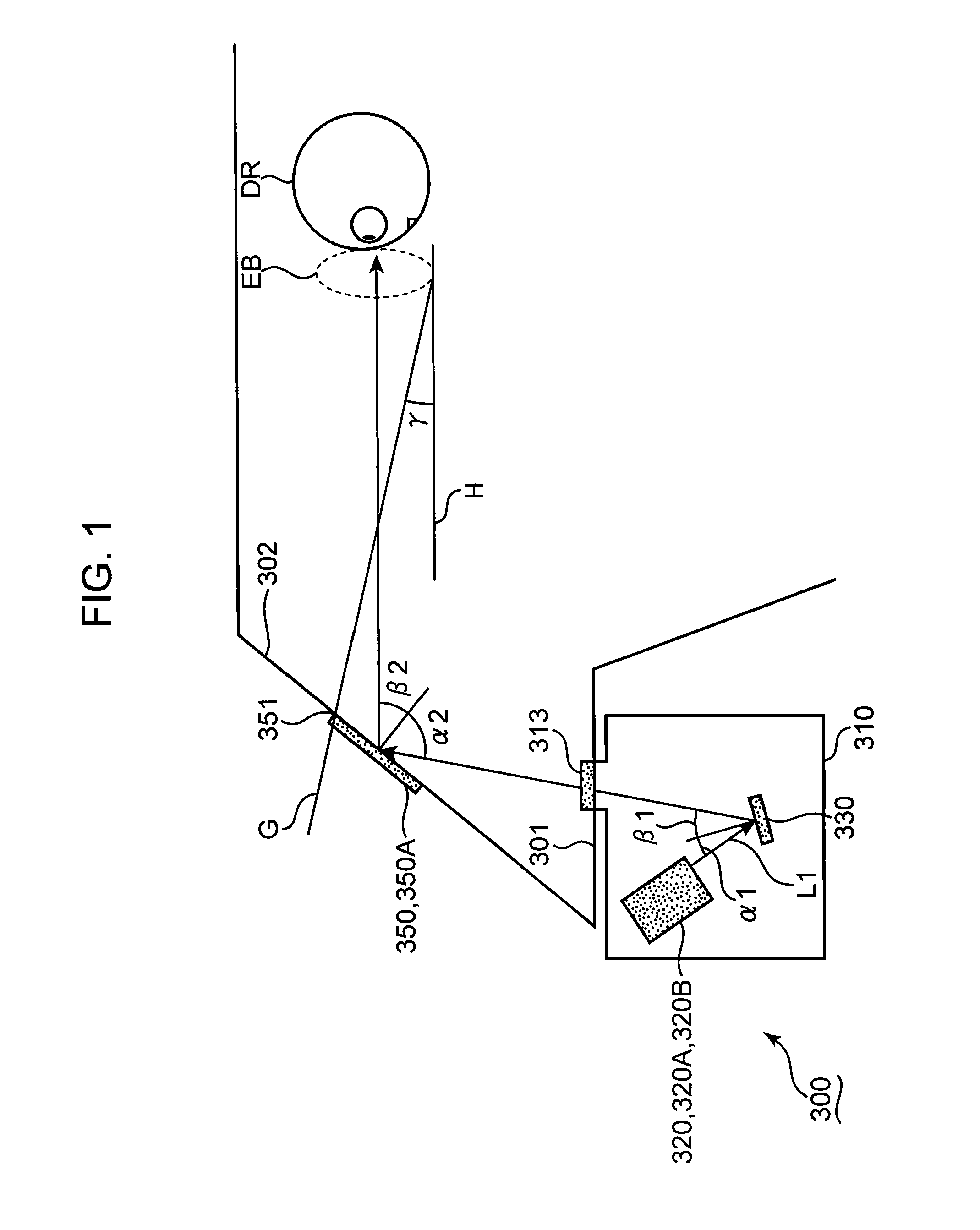
[0084]FIG. 1 is a schematic view of an exemplary HUD (head-up display) according to the first embodiment. An incident angle on a hologram combiner of the HUD according to the present embodiment is designed to be larger than its diffraction angle, in order to resolve the surface reflection problem and display high quality images.

[0085]The HUD 300 shown in FIG. 1 comprises an HUD optical unit 310 which is situated inside a dashboard of a vehicle 301. The HUD optical unit 310 stores a display part 320 and a correcting element 330. An opening 313 is formed on the HUD optical unit 310. The display part 320 creates display light L1 which is emitted through the opening 313. In the present embodiment, the HUD optical unit 310 is exemplified as the display unit.

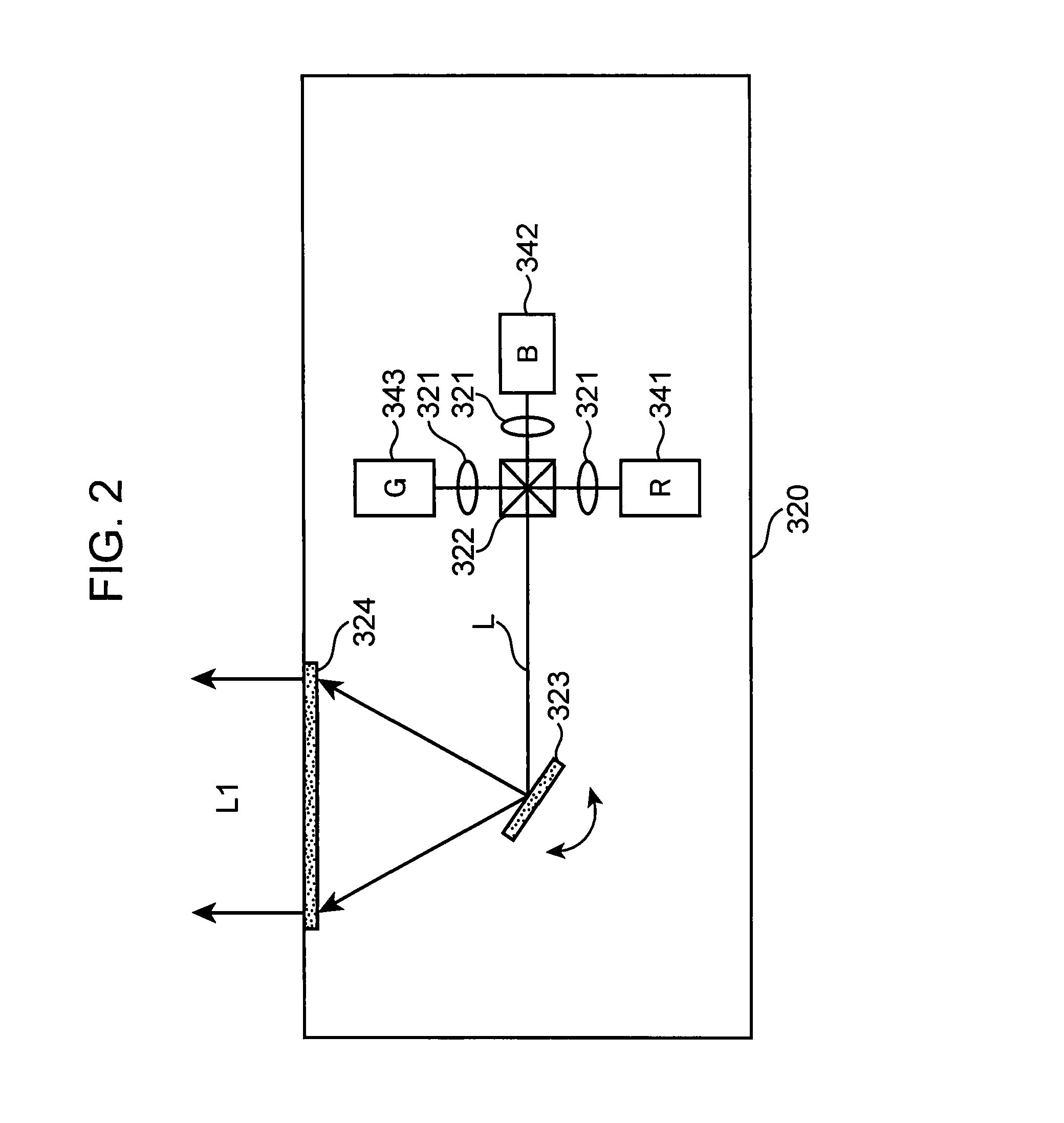
[0086]The display part 320 generates and emits the display light L1 to display an image, which contains driving information (a speedometer and / or map information), to a driver DR. In the present embodiment, the display part 320 two-di...

second embodiment

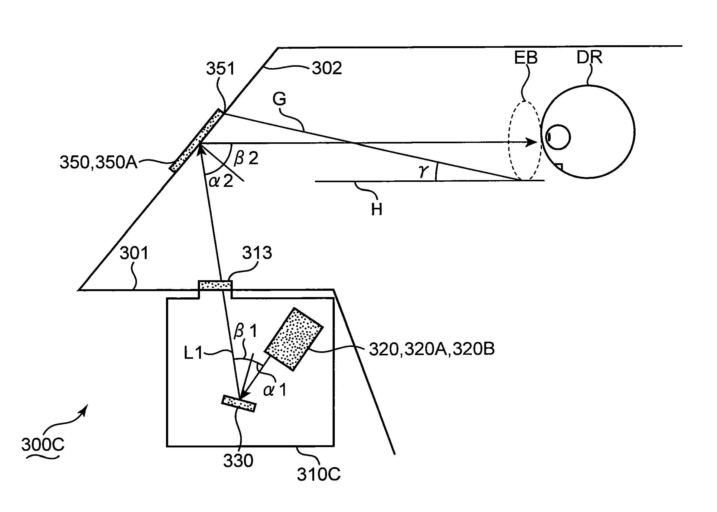
[0162]FIG. 12 shows a schematic view of an HUD which is exemplified as the transmissive display device according to the second embodiment. The same components as the first embodiment are labeled with the same reference numerals. Differences from the first embodiment are described with reference to FIGS. 1 and 12. Descriptions about the same components as the first embodiment are omitted here. The descriptions about the first embodiment may be suitably incorporated into components which are not described below.

[0163]The incident angle at the hologram combiner of the HUD according to the second embodiment is set to be smaller than the diffraction angle of the hologram combiner, unlike the first embodiment. Consequently, the surface reflection problem is resolved to improve quality of an image which is presented to the driver.

[0164]The HUD 300C comprises the hologram combiner 350 or 350A, which is situated on the front windscreen 302 of the vehicle 301, and the HUD optical unit 310C, w...

third embodiment

[0179]FIG. 15 shows a schematic view of an HUD which is exemplified as a transmissive display device according to the third embodiment. The same components as the second embodiment are labeled with the same reference numerals. Differences from the second embodiment are described with reference to FIG. 15. Descriptions about the components as the first and / or second embodiments are omitted here. The descriptions in the context of the first and / or second embodiments may be suitably incorporated to components which are not described below.

[0180]The incident angle on the hologram combiner of the HUD according to the third embodiment is set to be smaller than the diffraction angle of the hologram combiner, like the second embodiment. Consequently, the surface reflection problem is resolved to improve quality of the image which is presented to the driver.

[0181]The HUD 300D comprises a hologram combiner 350D which is situated on the front windscreen 302D of the vehicle 301, in addition to ...


PUM


Abstract

A transmissive display device includes: a light source which outputs light; a display part which receives the light from the light source and generates display light representing an image; a deflecting element which changes a direction of the display light emitted from the display part; and a transmissive reflector which reflects, towards a user, light of a wavelength included in the display light emitted from the display part, and transmits light of other wavelengths. An angle formed by a straight line, which extends between an upper edge of an incident area of the display light on the transmissive reflector and a lower portion of an eyebox which is defined as a visible range of the reflected light from the transmissive reflector, with respect to a horizontal line is smaller than a difference between an emission angle and an incident angle of the display light at the transmissive reflector.

Description

TECHNICAL FIELD[0001]The present invention relates to a transmissive display device which displays a superimposed image over an ambient outlook that is viewed through a transmissive display portion so that a user views an image and the ambient outlook together.BACKGROUND OF THE INVENTION[0002]A driver driving a vehicle such as an automobile has to safely and quickly perform various driving operations such as understanding what happens outside the vehicle, reading information from display devices of the vehicle and performing driving actions. Therefore, it is desirable that vehicle information sent from the display device is readable in a necessary movement range of the driver's viewpoint for understanding circumstances outside the vehicle while driving. For example, an image display device desirably irradiates light onto a part of a transparent plate such as the front windscreen of the vehicle to display texts and / or images.[0003]Various devices such as a head-up display (hereinafte...

Claims


Application Information

Patent Timeline
Patent Type & Authority Patents(United States)
IPC IPC(8): G02B27/14G02B27/01
CPCG02B27/0101B60K35/00B60K2350/2043B60K2350/2052B60K2350/941G02B5/32G02B27/0103G02B2027/012G09G3/025G09G2320/041H04N9/3129B60K2370/339B60K2370/334B60K2370/81
Inventor SUGIYAMA, KEIJIKASAZUMI, KENICHIYAMAMOTO, KAKUYAKUROZUKA, AKIRAITOH, TATSUOSHIKII, SHINICHI
Owner PANASONIC CORP
Why Eureka
Try Eureka