Motorized diffuser

a motorized diffuser and diffuser technology, applied in lighting and heating apparatus, ventilation systems, heating types, etc., can solve the problems of complex disassembly and assembly

Inactive Publication Date: 2014-08-19
OMNIVENT CORP
View PDF19 Cites 11 Cited by
  • Summary
  • Abstract
  • Description
  • Claims
  • Application Information

AI Technical Summary

Benefits of technology

[0005]Therefore, the present invention has been made in view of the above-mentioned problems, and the present invention provides a motorized diffuser or a diffuser-cone for cooling / heating or ventilation, in which the diffuser is opened only for use and is employed for cooling / heating through proportional air-volume control, and thus can greatly reduce an initial investment cost and energy consumption, compared to a VAV system. Furthermore, in a case where the diffuser is employed for ventilation facility of a house, an automatic open / close function of the diffuser allows an actual space requiring ventilation to be ventilated, thereby greatly reducing fan power. Also, it does not require a ceiling maintenance hole, so that a ceiling can be beautifully configured. Meanwhile, there is no obstruction to the flow passage, thereby removing the possibility of pollution to a driving part. Moreover, the diffuser has a simple configuration and requires only simple maintenance.
[0006]Especially, the diffuser according to the present invention has a performance superior to the costly VAV system, can reduce an initial investment cost up to 50% or more, and can reduce a driving cost for the use. Also, the diffuser can selectively ventilate a required space while a conventional system ventilates the entire house as well as a specific room requiring ventilation. Thus, it is possible to greatly reduce the consumption of electric energy.Technical solution

Problems solved by technology

Such a structure has a problem in that for maintenance, disassembling and assembling are complicated to perform, and also, an additional maintenance hole has to be provided in a ceiling.

Method used


Image

  • Motorized diffuser
  • Motorized diffuser
  • Motorized diffuser

Examples


Embodiment Construction

[0017]Hereinafter, preferred embodiments of the present invention will be described with reference to the accompanying drawings. However, the present invention is not limited thereto.

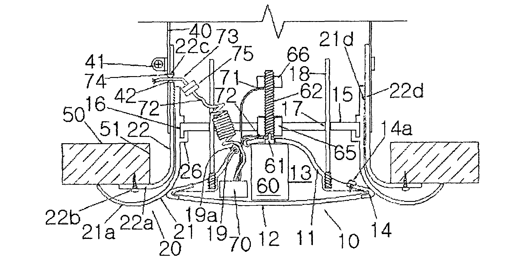
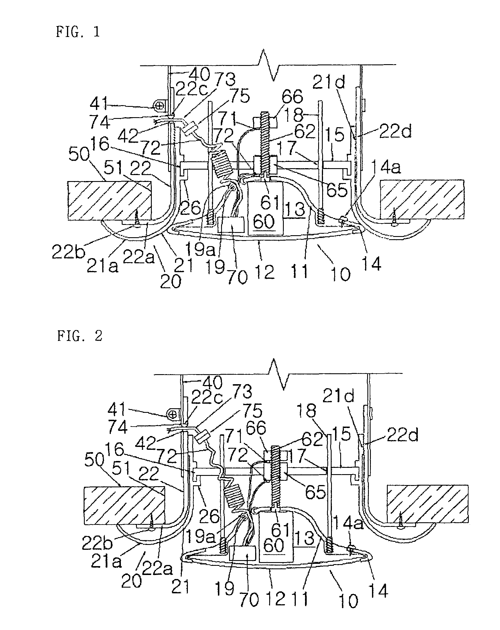
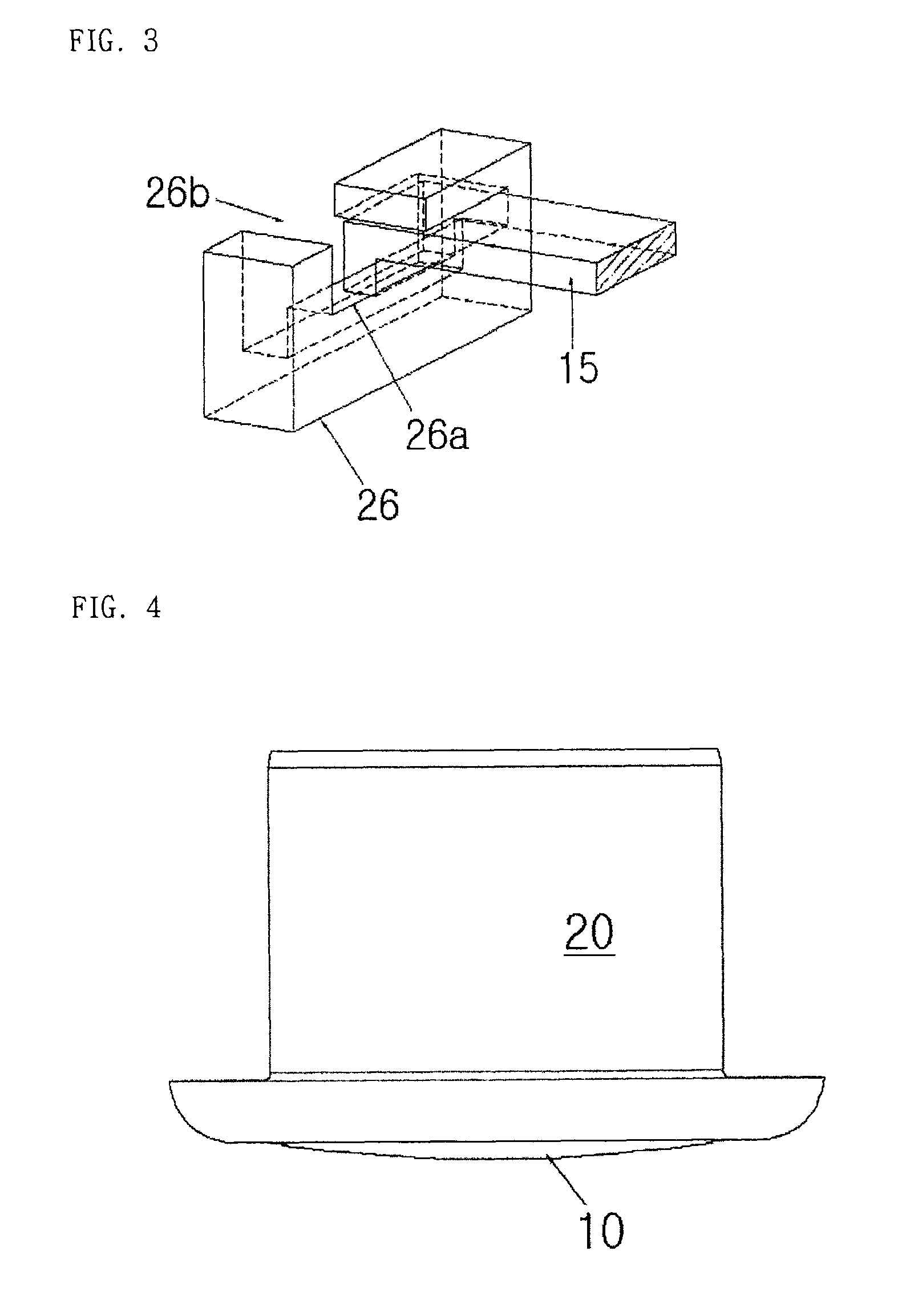
[0018]FIGS. 1 and 2 are cross-sectional views illustrating a state where a diffuser according to one embodiment of the present invention is provided in a diffuser mounting hole 51 of a ceiling 50 and operated; FIG. 3 is a partial perspective view illustrating an example of the diffuser shown in FIGS. 1 and 2, in which a fixing-supporting member and an inner casing are coupled; and FIGS. 4 to 7 are views illustrating a configuration of a diffuser according to another embodiment of the present invention.

[0019]The diffuser shown in FIGS. 1 and 2 include a diffuser cone 10 with a square- or circular-cross section, and a diffuser casing 20, in a similar manner to a conventional diffuser. The diffuser casing 20 include an outer casing 22 fixed at a duct, and an inner casing 21 having an outer coupling portion...


PUM


Abstract

Disclosed is a motorized diffuser which is shut when not in use and which reduces energy consumption in a building, eliminates the necessity of a maintenance hole, prevents contamination, has a simple configuration, and enables easy maintenance when applied in a cooling / heating system adopting a proportional air flow control scheme. According to the disclosed diffuser, a diffuser cone includes: a diffuser cone body which forms a fluid passage on the outer surface thereof which is disposed between the diffuser cone body and a diffuser casing when the diffuser cone is opened; a diffuser cone cover fixed to the diffuser cone body such that the diffuser cone cover can be assembled / disassembled to / from the diffuser cone body with a space therebetween; and a motor means fixedly installed in the space.

Description

CROSS-REFERENCE TO RELATED APPLICATIONS[0001]This is a U.S. national stage application of International Application No. PCT / KR2009 / 002566, filed on 14 May 2009. Priority under 35 U.S.C. 119(a) and 35 U.S.C. 365(b) is claimed from Korean Application No. KR10-2009-0004403, filed 20 Jan. 2009, the disclosure of which is also incorporated herein by reference.TECHNICAL FIELD[0002]The present invention relates to a motorized diffuser for cooling / heating or ventilation, which is provided in a ceiling indoors by being connected to an inside duct.BACKGROUND ART[0003]A variable air volume control box (VAV box) and a thermostat have been conventionally provided and generally used in order to control an air volume appropriate for a region to be air conditioned. Also, based on a nationally administered law on apartment house ventilation, many apartments have been equipped with ventilation equipment for forced ventilation.[0004]In a configuration where an opening rate is controlled by driving a m...

Claims


Application Information

Patent Timeline
Patent Type & Authority Patents(United States)
IPC IPC(8): F24F7/00F24F13/062F24F13/14
CPCF24F13/062F24F2013/1433F21S2/00F21V17/101F21V29/89
Inventor KIM, SONG, YEE
Owner OMNIVENT CORP
Why Eureka
Try Eureka