Motorized diffuser

a motorized diffuser and diffuser technology, applied in lighting and heating apparatus, ventilation systems, heating types, etc., can solve the problems of complex disassembly and assembly

Inactive Publication Date: 2011-11-10
OMNIVENT CORP
View PDF15 Cites 15 Cited by
  • Summary
  • Abstract
  • Description
  • Claims
  • Application Information

AI Technical Summary

Problems solved by technology

Such a structure has a problem in that for maintenance, disassembling and assembling are complicated to perform, and also, an additional maintenance hole has to be provided in a ceiling.

Method used


Image

  • Motorized diffuser
  • Motorized diffuser
  • Motorized diffuser

Examples


Embodiment Construction

[0016]Hereinafter, preferred embodiments of the present invention will be described with reference to the accompanying drawings. However, the present invention is not limited thereto.

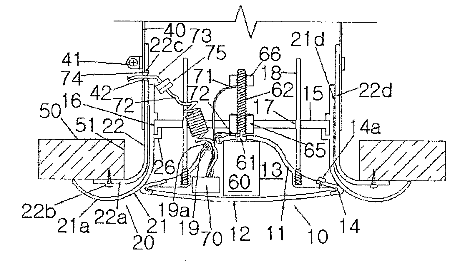
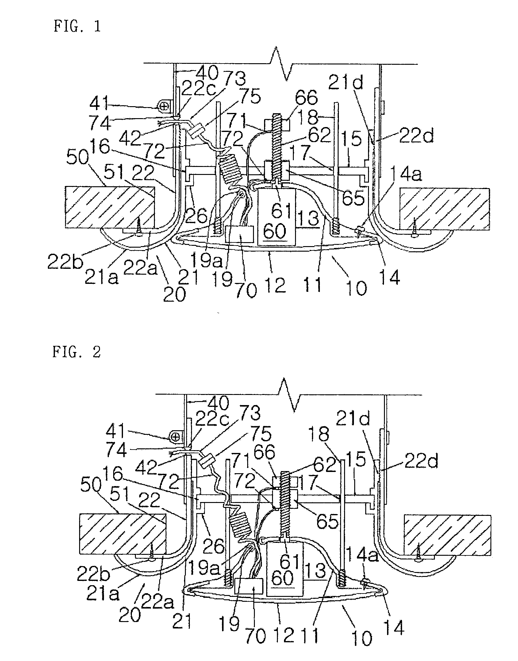
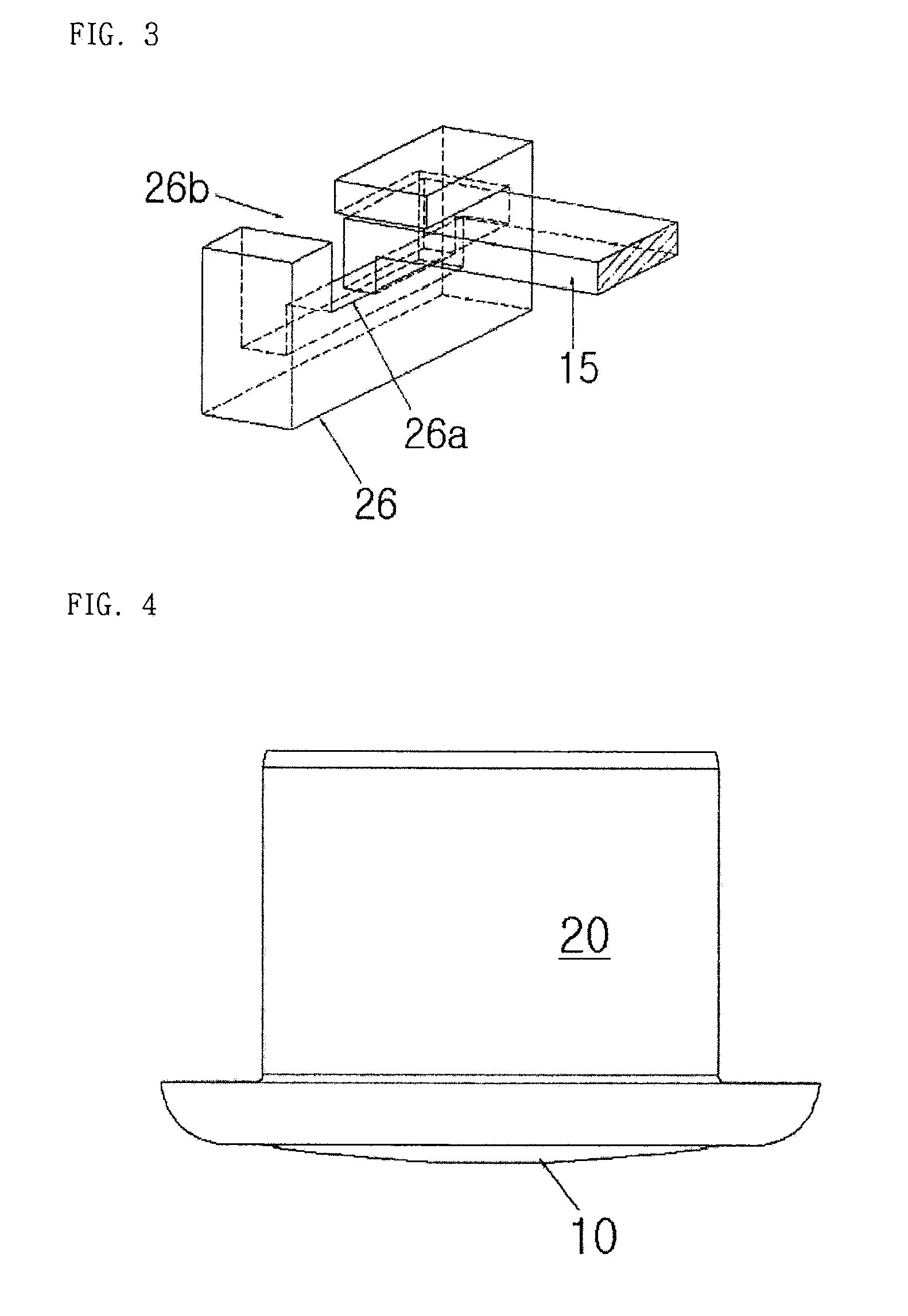
[0017]FIGS. 1 and 2 are cross-sectional views illustrating a state where a diffuser according to one embodiment of the present invention is provided in a diffuser mounting hole 51 of a ceiling 50 and operated; FIG. 3 is a partial perspective view illustrating an example of the diffuser shown in FIGS. 1 and 2, in which a fixing-supporting member and an inner casing are coupled; and FIGS. 4 to 7 are views illustrating a configuration of a diffuser according to another embodiment of the present invention.

[0018]The diffuser shown in FIGS. 1 and 2 include a diffuser cone 10 with a square- or circular-cross section, and a diffuser casing 20, in a similar manner to a conventional diffuser. Especially, in the present embodiment, an outer casing 22 of the diffuser casing 20 is connected to a duct 40 and is fixed...


PUM


Abstract

Disclosed is a motorized diffuser which is shut when not in use and which reduces energy consumption in a building, eliminates the necessity of a maintenance hole, prevents contamination, has a simple configuration, and enables easy maintenance when applied in a cooling/heating system adopting a proportional air flow control scheme. According to the disclosed diffuser, a diffuser cone includes: a diffuser cone body which forms a fluid passage on the outer surface thereof which is disposed between the diffuser cone body and a diffuser casing when the diffuser cone is opened; a diffuser cone cover fixed to the diffuser cone body such that the diffuser cone cover can be assembled/disassembled to/from the diffuser cone body with a space therebetween; and a motor means fixedly installed in the space.

Description

TECHNICAL FIELD[0001]The present invention relates to a motorized diffuser for cooling / heating or ventilation, which is provided in a ceiling indoors by being connected to an inside duct.BACKGROUND ART[0002]A variable air volume control box (VAV box) and a thermostat have been conventionally provided and generally used in order to control an air volume appropriate for a region to be air conditioned. Also, based on a nationally administered law on apartment house ventilation, many apartments have been equipped with ventilation equipment for forced ventilation.[0003]In a configuration where an opening rate is controlled by driving a motor, the motor is provided in a flow passage or provided outside a diffuser or a duct. Such a structure has a problem in that for maintenance, disassembling and assembling are complicated to perform, and also, an additional maintenance hole has to be provided in a ceiling.DISCLOSURETechnical Problem[0004]Therefore, the present invention has been made in ...

Claims


Application Information

Patent Timeline
Patent Type & Authority Applications(United States)
IPC IPC(8): F24F7/00
CPCF24F2013/1433F24F13/062F21S2/00F21V17/101F21V29/89
Inventor KIM, SONG YEE
Owner OMNIVENT CORP
Why Eureka
Try Eureka