Wireless power transmission system

a power transmission system and wireless technology, applied in the direction of transformers, inductances, transportation and packaging, etc., can solve the problems of unwanted interference with further electronic devices, and achieve the effect of reducing the magnetic far-field, efficient manufacturing of the base unit, and efficient cancellation of the magnetic far-field

Active Publication Date: 2014-08-19
KONINKLIJKE PHILIPS ELECTRONICS NV
View PDF8 Cites 81 Cited by
  • Summary
  • Abstract
  • Description
  • Claims
  • Application Information

AI Technical Summary

Benefits of technology

[0007]The basic idea of the invention is to provide a wireless electrical power transmission system which enables to transfer power to a device using induction generated by a magnetic field, where the magnetic field is concentrated in the region near the device, i.e. in the magnetic near-field, while the far-field is cancelled-out by a second magnetic field, which advantageously reduces the magnetic stray field and thus enhances the electromagnetic compatibility (EMC) of the system.
[0037]To enable measuring the far-field more precisely and thus to further enhance the reduction of the magnetic far-field, the sensor is most preferably provided in a defined distance to the transmission circuit. For instance, the sensor may be arranged on the periphery of said transmission area or of the base unit, or it may even be provided in a separate unit, connected to the base unit, but which may be placed in a defined distance to the base unit.

Problems solved by technology

Although the known system allows to wirelessly recharge such a device, the inductor coils in the base unit generate a rather large magnetic stray field which causes problems in EMC-sensitive environments and may cause unwanted interference with further electronic devices.

Method used


Image

  • Wireless power transmission system
  • Wireless power transmission system
  • Wireless power transmission system

Examples


second embodiment

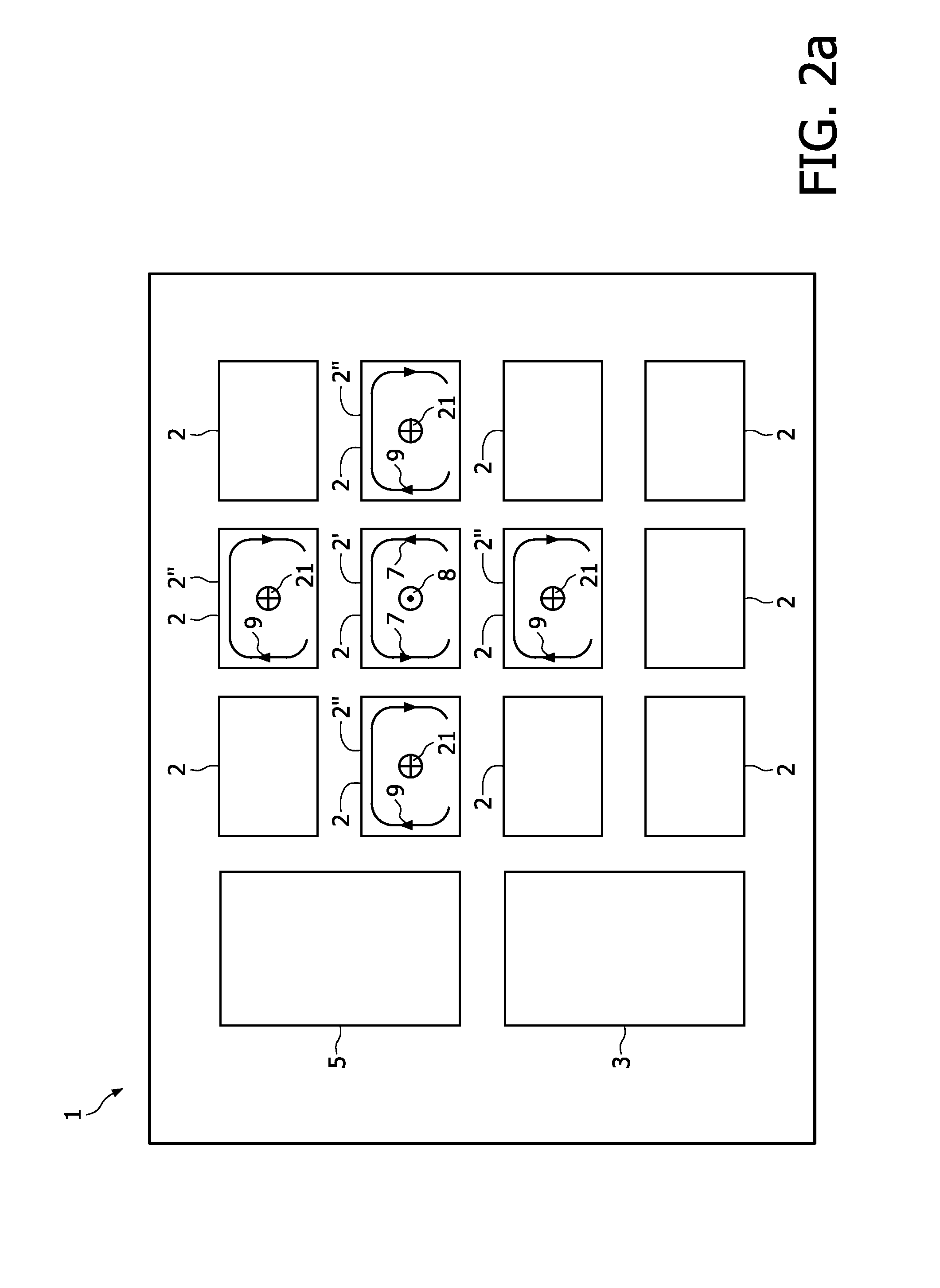
[0053]Further details of the invention are explained with reference to the FIGS. 2a-2c, which show schematic plan views of a wireless power transmission system in multiple operational states. Since alternating fields are used to induce a current in the receiving coil 11, FIG. 2a-2c show “snapshots” of the system at a given moment of time, to clarify the operation of the system.

[0054]According to the embodiment of FIG. 2a, a base unit 1 with an array of 3×4 coils 2 is provided to wirelessly transfer power to one or more devices 10 (not shown). One of the coils 2 is operated as a transmission circuit 2′ by the controller 3 to transfer power to a device 10 (not shown), arranged on top of the transmission circuit 2′. The transmission circuit 2′ is therefore supplied by the controller 3 with a first signal having a first phase, i.e. according to the “snapshot” of FIG. 2 in a first direction, as indicated by the arrows 7 and thus a first magnetic field 8 with a first phase, i.e. a first d...

third embodiment

[0069]To further enhance the compensation efficiency, it is possible to provide a separate controllable compensation power supply unit 45, as shown in FIG. 4a-4c. FIG. 4a shows a schematic plan view of a third embodiment in an operational state. The basic set up of the power transmission system according to the embodiment of FIG. 4a corresponds to the embodiment of FIG. 2a, especially the arrangement of the coils 2.

[0070]Each coil 2 can be connected either to the power supply unit 5, which provides the transmission coils 2′ with an ac voltage for power transmission (Ugen) or to the controllable compensation power supply 45 for providing an ac compensation voltage (Uc) to the compensation circuits 2″ using switches 31, as can be taken from FIG. 4b, which shows a schematic circuit diagram of the embodiment according to FIG. 4a. The controller 3 sets the compensation voltage according to equation (6), depending on the number of activated transmission circuits 2′ and compensation circui...

fourth embodiment

[0073]FIG. 5 shows a wireless power transmission system according to the invention in a schematic plan view in an operational state. In contrast to the embodiment of FIG. 2a, a dedicated compensation circuit 52 is provided on a periphery of the base unit 1, forming a transmission area, in which the coils 2 are arranged. The compensation circuit 52 is formed by a coil with multiple windings for generating the second magnetic field 21, which provides compensation in the magnetic far-field for the first magnetic field 8, generated by the one or more transmission circuits 2′. The compensation circuit 52 has the same number of turns as each of the coils 2. The coils 2 and the compensation circuit 52 are provided with an ac voltage by power supply unit 5.

[0074]FIGS. 6a and 6b show a schematic circuit diagram of the embodiment of FIG. 5. Each coil 2 can be switched to the ac supply voltage, provided by power supply unit 5. The compensation circuit 52 is connected to the same power supply u...


PUM


Abstract

A Wireless power transmission system comprises a base unit (1) with multiple magnetic field generator circuits and a device (10), separable from said base unit (1) having a receiving inductor, adapted to receive power inductively when said device (10) is in proximity to one of said generator circuits, wherein said base unit (1) comprises a controller (3), configured to determine a transmission circuit (2′) from said generator circuits when said receiving inductor is in proximity to said transmission circuit (2′), whereupon said transmission circuit (2′) is operated to generate a first magnetic field (8), having a first phase, to induce a current in said receiving inductor and at least one of the remaining generator circuits is operated as a compensation circuit (2″, 52, 82) to generate a second magnetic field (21), having an opposite phase to said first phase.

Description

FIELD OF THE INVENTION[0001]The invention relates to a wireless power transmission system and a method for operating the same.BACKGROUND OF THE INVENTION[0002]Electronic devices, which are “mobile” or portable, are being used today for various commercial or personal applications. Examples of such devices include mobile phones, notebook computers, personal digital assistants (PDA) or portable music players. The afore-mentioned devices are usually powered by a rechargeable battery, which has to be recharged periodically to keep the device operational. For recharging or for supplying external power, each device normally has a dedicated power supply unit, which has to be connected to the device and to a wall power outlet. Since most devices are not compatible with each other, a dedicated power supply unit is needed for each device.[0003]Due to the fact that the total number of such devices used increases, wireless power sources have been developed, which reduce time and effort of the re...

Claims


Application Information

Patent Timeline
Patent Type & Authority Patents(United States)
IPC IPC(8): H02J17/00
CPCH02J5/005H01F17/0006H01F38/14H02J50/402H02J50/90H02J50/10H02J50/80H02J50/70H04B5/0087
Inventor SAUERLAENDER, GEORGWAFFENSCHMIDT, EBERHARD
Owner KONINKLIJKE PHILIPS ELECTRONICS NV
Why Eureka
Try Eureka