
Simplified current sense for buck LED driver

a buck led driver and current sense technology, applied in the direction of electric variable regulation, process and machine control, instruments, etc., can solve the problem of dropping across the sense resistor

Active Publication Date: 2014-08-19
POWER INTEGRATIONS INC
View PDF5 Cites 17 Cited by
  • Summary
  • Abstract
  • Description
  • Claims
  • Application Information

AI Technical Summary

Benefits of technology

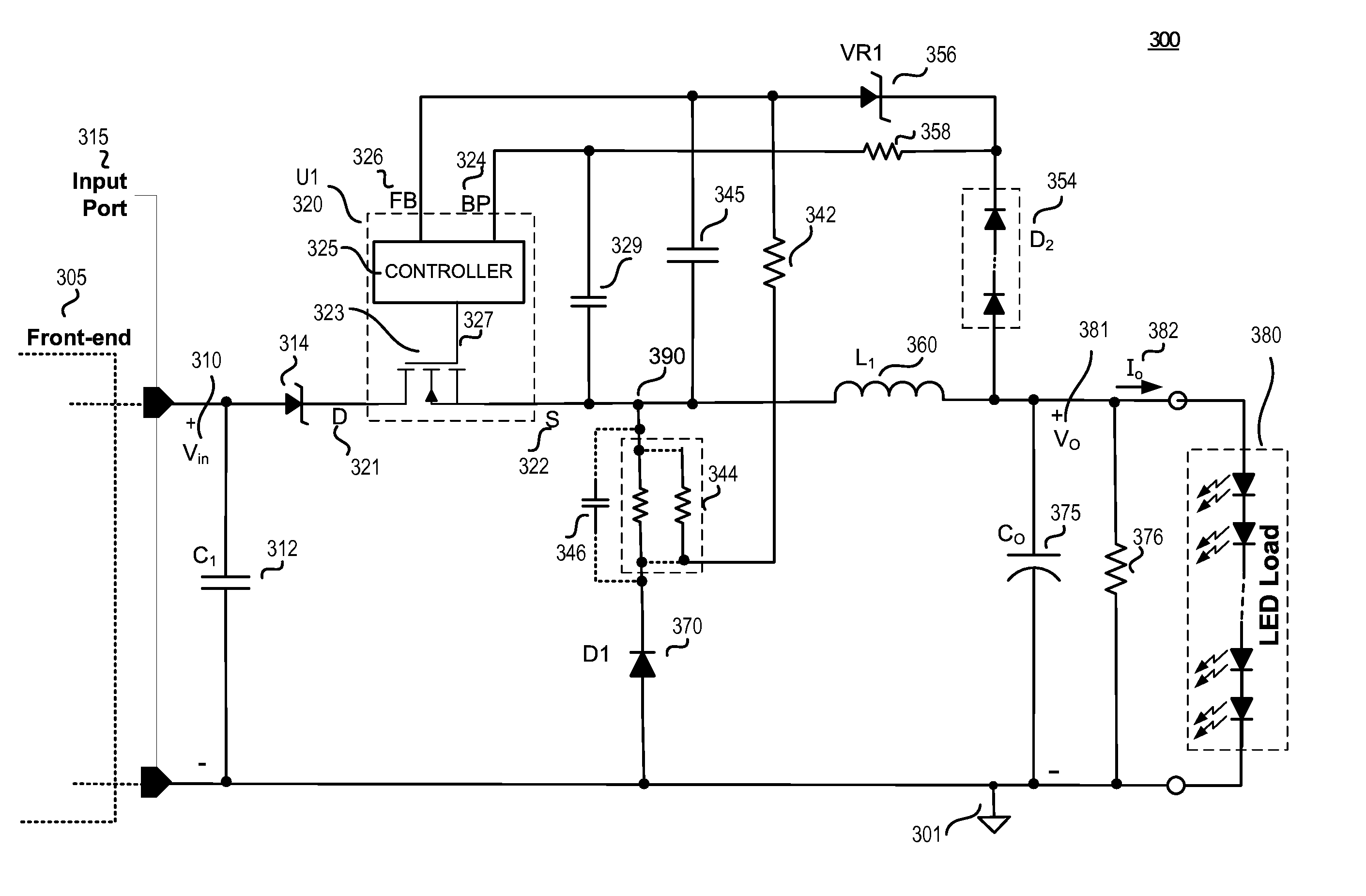
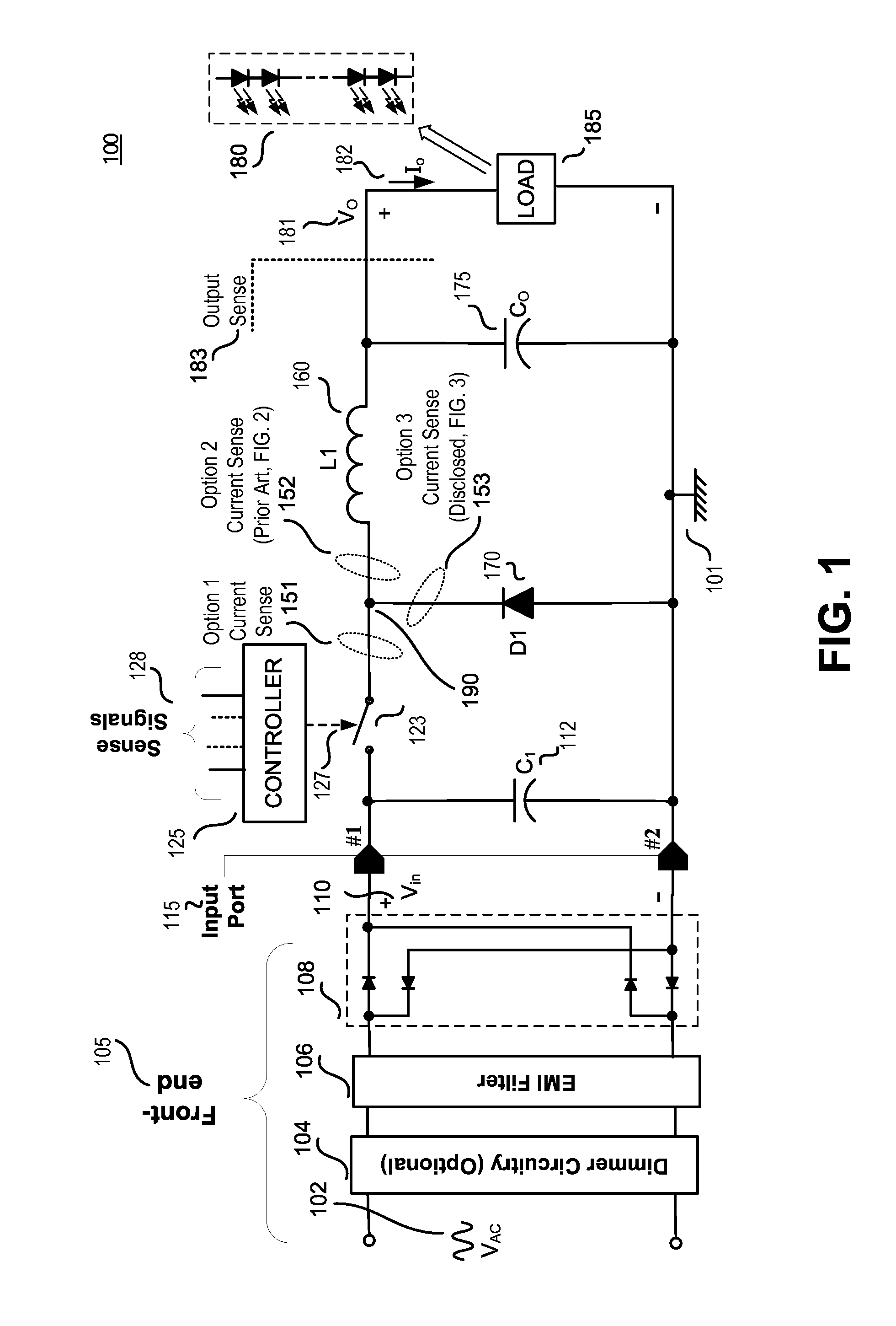
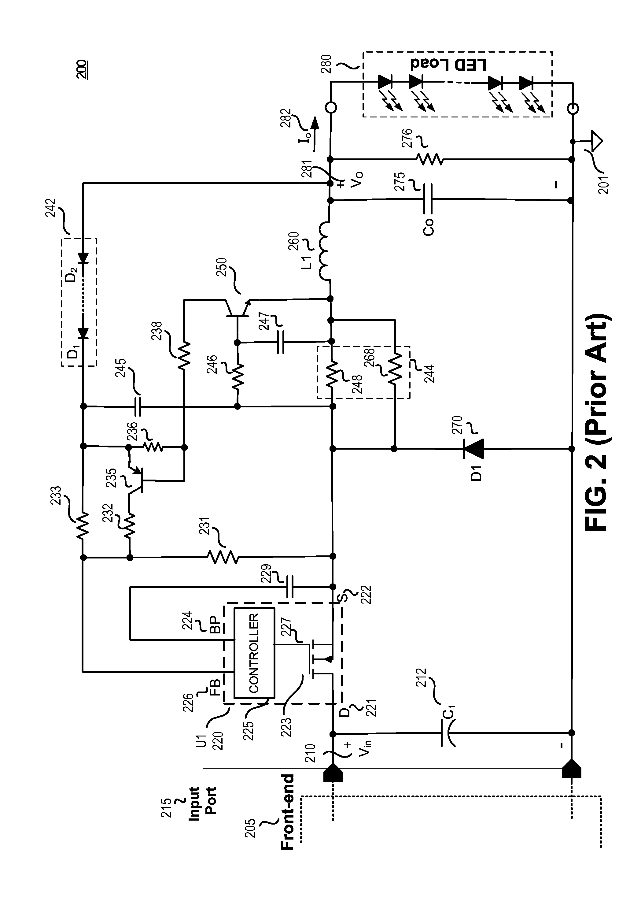
The present invention relates to non-isolated buck converters used as power converters for electronic devices. More specifically, the invention provides a circuit and method for regulating the output voltage or current of a non-isolated buck converter through the use of a feedback signal from the output of the converter. The feedback signal can be measured using a sense resistor or an opto-coupler, and the invention provides various methods for level shifting the voltage across the resistor to interface with the controller. The technical effect of the invention is to provide a more efficient and compact solution for regulating the output of a non-isolated buck converter, which is commonly used in various lamp types such as CFLs, Halogen lamps, or LED bulbs.

Problems solved by technology

However, the voltage drop across the sense resistor is typically large and often referenced to a voltage level different than that of the power converter controller.

Method used


Image

  • Simplified current sense for buck LED driver
  • Simplified current sense for buck LED driver
  • Simplified current sense for buck LED driver

Examples


Embodiment Construction

[0013]In the following description, numerous specific details are set forth in order to provide a thorough understanding of the present invention. It will be apparent, however, to one having ordinary skill in the art that the specific detail need not be employed to practice the present invention. In other instances, well-known materials or methods have not been described in detail in order to avoid obscuring the present invention.

[0014]Reference throughout this specification to “one embodiment”, “an embodiment”, “one example” or “an example” means that a particular feature, structure or characteristic described in connection with the embodiment or example is included in at least one embodiment of the present invention. Thus, appearances of the phrases “in one embodiment”, “in an embodiment”, “one example” or “an example” in various places throughout this specification are not necessarily all referring to the same embodiment or example. Furthermore, the particular features, structure...


PUM


Abstract

A current sense and feedback circuit is provided for a non-isolated Buck power converter to maintain constant current load regulation. The Buck converter may have a high side power switch and may include an input port, a switcher unit including a switch and a controller, an inductor coupled to the output, and a freewheeling diode for circulating the inductor current when the switch is open. The simplified current sense and feedback circuit of the power converter may include a current sense resistor module coupled to the freewheeling diode to provide a sense signal to the controller. The controller may also be coupled to the output of the power converter to sense an over voltage condition. The simplified current sense and feedback circuit may provide output regulation while maintaining a low component count, small size, and low loss that makes the power converter suitable for use in compact design applications.

Description

BACKGROUND[0001]1. Field[0002]The present disclosure relates generally to power converters and, more specifically, to non-isolated Buck converters.[0003]2. Description of Related Art[0004]Conventional wall outlets generally deliver a high voltage alternating current (ac) power that needs to be transformed to direct current (dc) power before being used to power many electronic devices. Switched mode power converters are commonly used due to their high efficiency, small size, low weight, and safety protection features, to convert the high voltage ac power to a regulated dc power. For example, switch mode power converters are commonly used in drive circuitry in the lighting industry to provide dc power for various lamp types, such as compact florescent lamps (CFLs), Halogen lamps, or light emitting diode (LED) bulbs.[0005]Output regulation in a switch mode power converter is usually provided by sensing a feedback signal from the output of the converter and controlling the power convert...

Claims


Application Information

Patent Timeline
Patent Type & Authority Patents(United States)
IPC IPC(8): H05B37/02
CPCH05B37/00H02M3/158H02M2001/0009H05B33/0815H05B33/0848H05B45/14H05B45/375H02M1/0009
Inventor DEL, CARMEN, JR., JOSE, R.
Owner POWER INTEGRATIONS INC
Learn More