Electronic endoscope

a technology of endoscope and endoscope, which is applied in the field of color reproduction, can solve problems such as discordance in the saturation of complementary color filters, and achieve the effect of good color reproduction

Inactive Publication Date: 2009-11-24
HOYA CORP
View PDF19 Cites 58 Cited by
  • Summary
  • Abstract
  • Description
  • Claims
  • Application Information

AI Technical Summary

Benefits of technology

[0015]According to the present invention, the matrix coefficient, which is used for color adjusting the color component signals, is changed based on the control signa...

Problems solved by technology

Accordingly, difference in the luminance brightness between some portions of the optical...

Method used


Image

  • Electronic endoscope
  • Electronic endoscope
  • Electronic endoscope

Examples


first embodiment

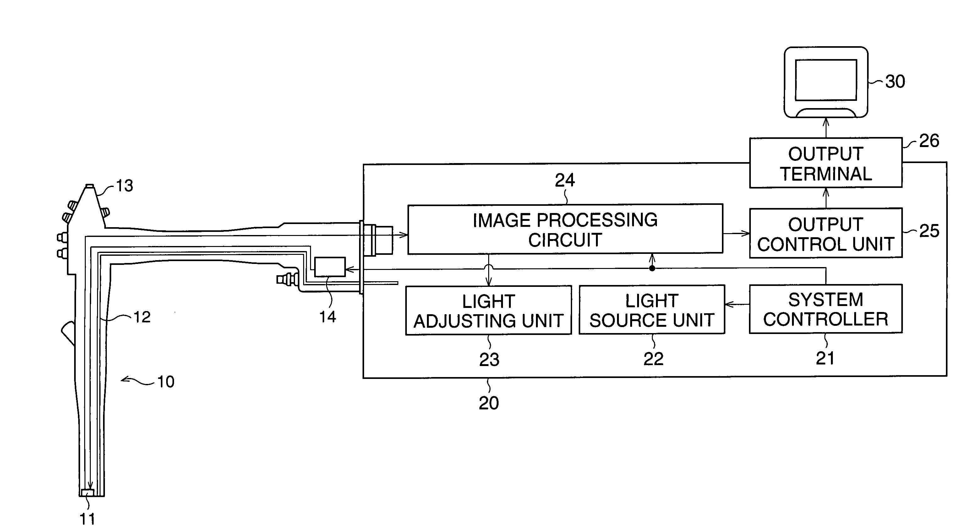
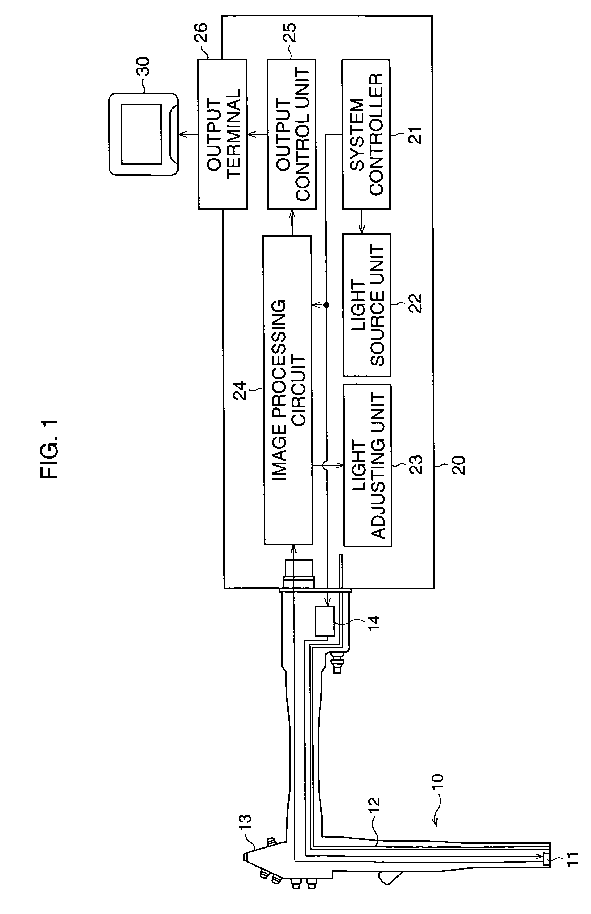
[0023]FIG. 1 is a block diagram of an electronic endoscope to which a first embodiment according to the present invention is applied. An electronic scope 10 includes a flexible tube. The scope 10 is connected to an image-signal processing device 20 in such a manner that the scope 10 is attachable to and detachable from the device 20. An image sensor 11, which includes an objective optical system and a CCD image sensor, is provided at the tip of the scope 10. Alight guide 12 passes through the scope 10. An emitting end of the light guide 12 is arranged at the distal end of the scope 10. Operating buttons are provided on a control portion 13 of the scope 10. The operating buttons include a freeze button, a copy button, a record button, and so on. Moving pictures are changed to still pictures by manipulating the freeze button. Still pictures are copied by the copy button. When a video printer and a VTR (not shown) are connected to the device 20, still pictures and moving pictures are r...

second embodiment

[0055]Note that, in the second embodiment, one element of the color matrix coefficient, for example only the element a21 of the secondline of the first row, is changed, in consideration of the calculation speed. However, other elements, which relate to the green color component, namely the element a22 of the second row or the second line, the element a23 of the third row and the second line, can be changed. Further, a plurality of elements (for example, all three elements which relate to the green color component) can be respectively changed by the corresponding expressions. Similarly, the color conversion may be performed changing the elements relating to the red color component or the elements relating to the blue color component.

[0056]According to the present invention, good color reproduction can be carried out at all times in an electronic endoscope which is provided with a color CCD.


PUM


Abstract

Analog pixel signals, which are read out from an image sensor, are subjected to predetermined signal processes, and are converted to digital pixel signals by an A/D converter. The digital pixel signals are separated to RGB signals. The RGB signals are multiplied by a predetermined color matrix coefficient. After that, luminance signals are extracted from the RGB signals. A light adjusting control signal for adjusting the quantity of light is calculated based on the luminance signals. The color matrix coefficient is changed based on the light adjusting control signal.

Description

BACKGROUND OF THE INVENTION[0001]1. Field of the Invention[0002]The present invention relates to color reproduction of an object of view in an electronic endoscope.[0003]2. Description of the Related Art[0004]Conventionally, there is an electronic endoscope which captures an object image by the color chip method, using a color CCD. An insert portion of the electronic endoscope is inserted into a body of a patient. A fiber bundle (light guide), which is a bundle of extra fine optical fibers, is penetrated through the insert portion. White illumination light, which is supplied from a light source device, is led to the tip of the insert portion by the light guide, and illuminates an object of view from the tip. The color CCD is provided with color chip filters having complementary colors (magenta, yellow, cyan, and green) which are arranged mosaically. Light reflected by the object is imaged on an image capturing plane of the color CCD through objective lenses. The imaged optical image...

Claims


Application Information

Patent Timeline
IPC IPC(8): H04N13/00H04N5/335G02B23/24A61B1/04A61B1/045H04N5/225H04N7/18H04N9/04H04N9/67
CPCH04N9/045A61B1/045H04N2005/2255H04N23/555H04N23/84H04N25/136
Inventor KOBAYASHI, HIROYUKI
Owner HOYA CORP
Why Eureka
Try Eureka