Spark plug including electrodes with low swelling rate and high corrosion resistance

a spark plug and electrode technology, applied in spark plug manufacturing, spark plugs, machines/engines, etc., can solve the problems of unexpected increase in the width of the spark gap, undesirable swelling and thermal mechanical stresses, and subsequent loss of engine power and performance, so as to reduce swelling and reduce swelling. the effect of swelling rate and adequate operating temperatur

Inactive Publication Date: 2014-08-26
FEDERAL MOGUL IGNITION
View PDF21 Cites 3 Cited by
  • Summary
  • Abstract
  • Description
  • Claims
  • Application Information

AI Technical Summary

Benefits of technology

[0011]The combination of the Cu alloy and the Ni alloy of the inventive electrodes and spark plugs provides both high thermal conductivity and reduced swelling rate, compared to the prior art electrodes and spark plugs. The inventive electrodes and spark plugs provide oxidation, erosion, and corrosion resistance; adequate operating temperatures; improved creep resistance; and reduced cracking, compared to the prior art electrodes and spark plugs. Thus, spark plugs of the present invention, including the Cu alloy and Ni alloy, provide improved performance during operation than the prior art spark plugs.

Problems solved by technology

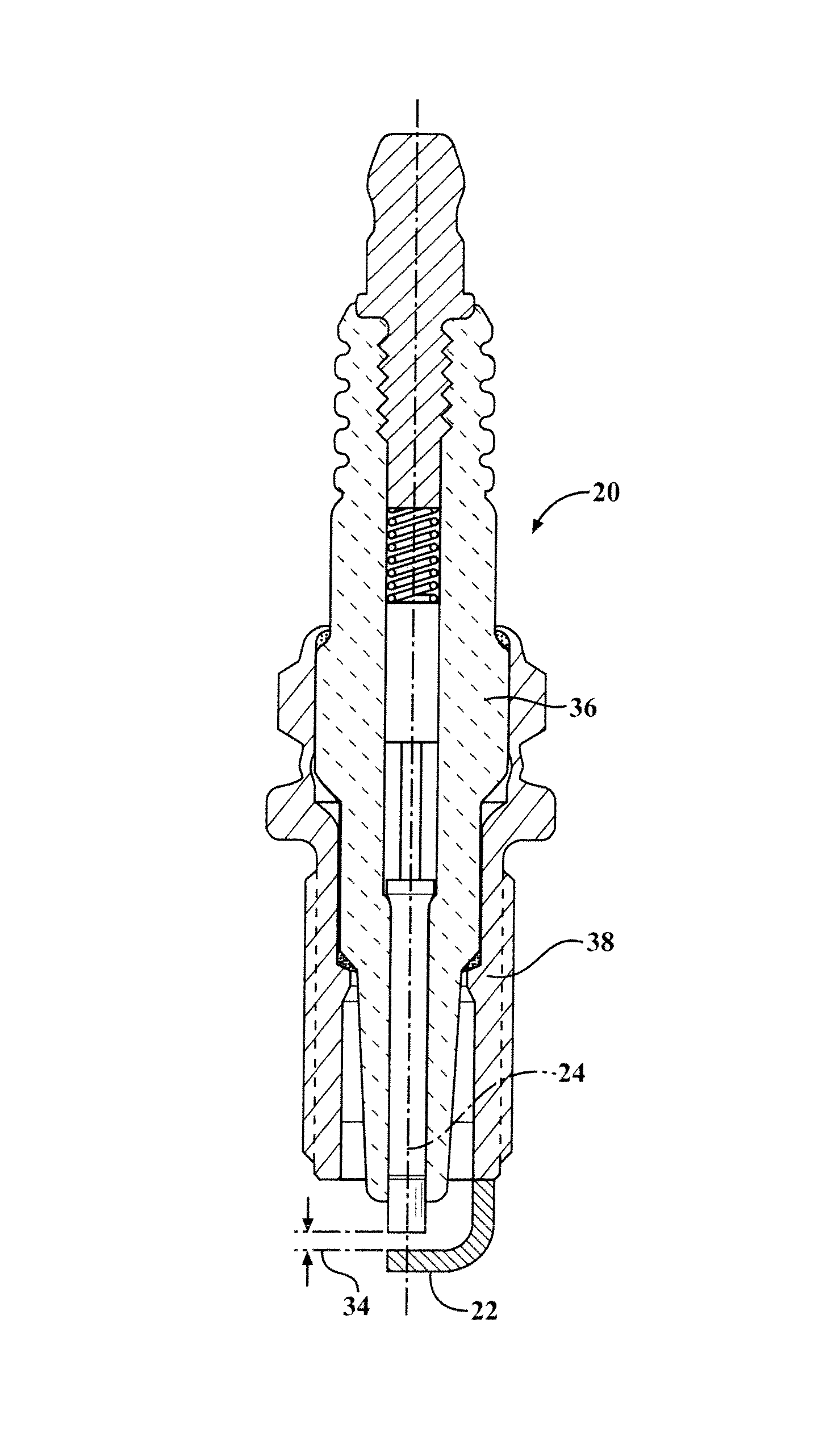
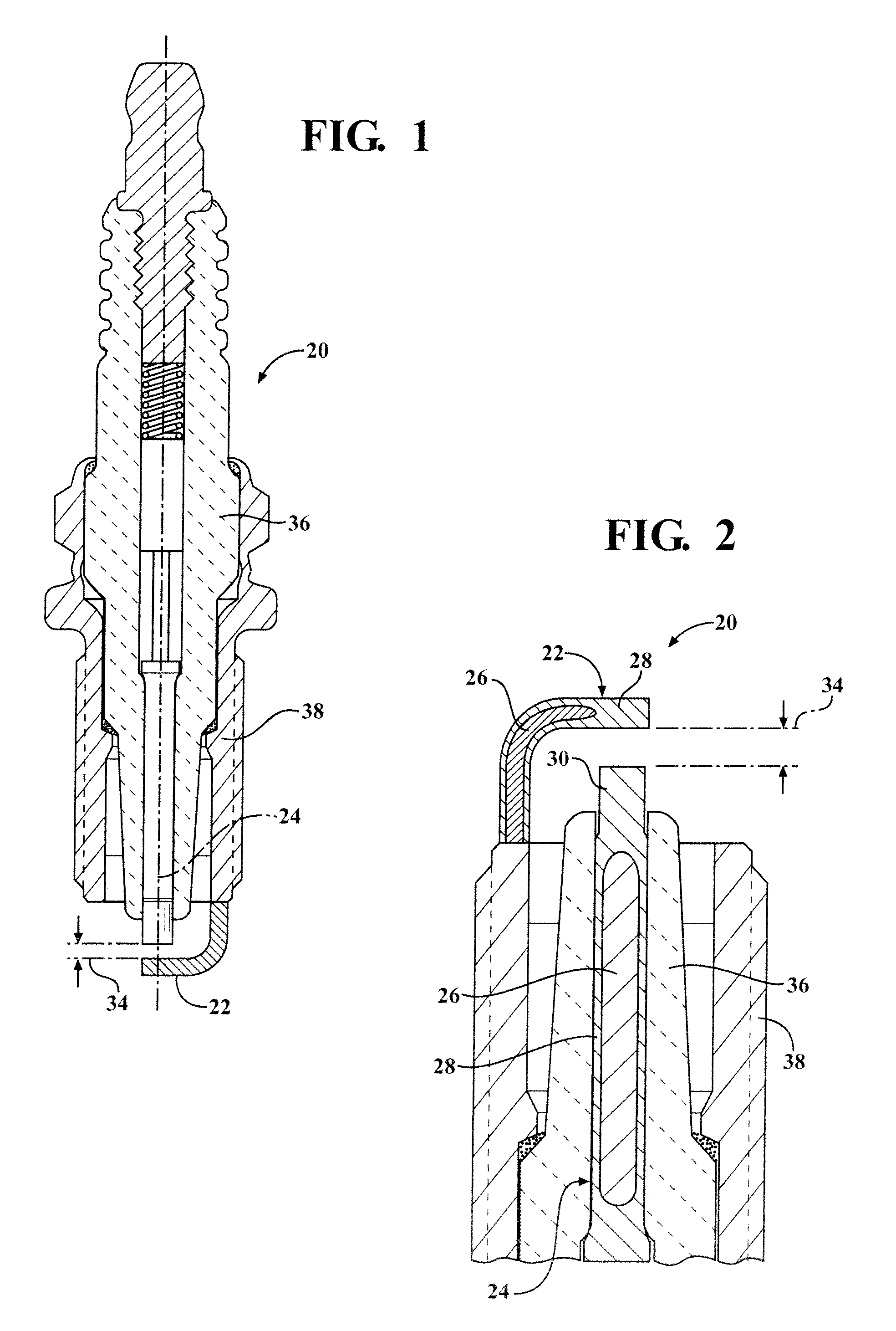
When the electrodes are not fabricated of appropriate materials, the extreme working conditions may gradually increase the width of the spark gap between the center electrode and ground electrode, and may induce the misfire of spark plugs and cause subsequent loss of engine power and performance.
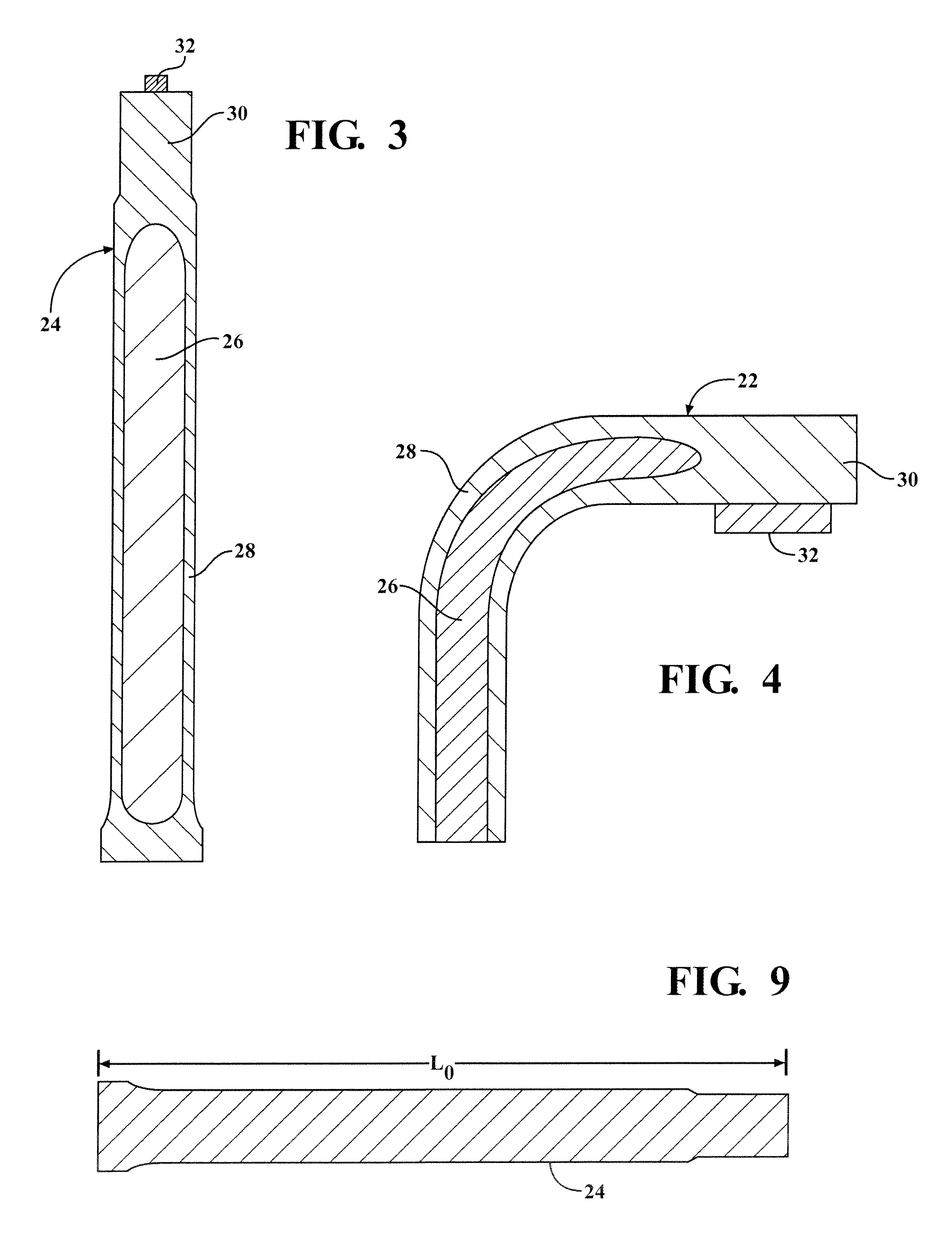
There is a significant difference in thermal expansion of the Cu core and the Ni clad, which causes undesirable swelling and thermal mechanical stresses.
The swelling may increase the width of the spark gap unexpectedly.
The Ni clad has a tension stress along the azimuthal direction which may cause cracking in the Ni clad and insulator. FIGS. 5 and 6 show deformation of the electrode and cracks due to thermal stress and creep, which may hinder the performance of the spark plug.

Method used


Image

  • Spark plug including electrodes with low swelling rate and high corrosion resistance
  • Spark plug including electrodes with low swelling rate and high corrosion resistance
  • Spark plug including electrodes with low swelling rate and high corrosion resistance

Examples


examples

[0053]Table 2 includes several example embodiments of the Cu alloy of the core 26 of the present invention and a comparative, prior art example of a Cu alloy used in an electrode of the prior art.

[0054]

TABLE 2Copper CoreCuZrCr(weight percent, wt %)(weight percent)(weight percent)Inventive98.81-99.050.05-0.150.0Example 1Inventive98.81-99.950.05-0.090.9-1.10Example 2Prior Art100.00.00.0Example 1

[0055]Table 3 includes three example embodiments of the Ni alloy of the clad 28 of the present invention and a comparative, prior art example of a Ni alloy used in an electrode of the prior art. In another embodiment, Inventive Example 5 may include at least one of Y in an amount of 0.01 weight percent to 0.1 weight percent, Zr in an amount of 0.01 weight percent to 0.2 weight percent and, Ti in an amount of 0.05 weight percent to 0.4 weight percent, and a balance of Ni. In other words, the Y, Zr, Ti may all be present in the Ni alloy, or less than all may be present in the Ni alloy.

[0056]

TABLE...


PUM

PropertyMeasurementUnit
weight percentaaaaaaaaaa

Abstract

A spark plug (20) includes a center electrode (24) and a ground electrode (22). The electrodes (22, 24) include a core (26) formed of a copper (Cu) alloy and a clad (28) formed of a nickel (Ni) alloy enrobing the core (26). The Cu alloy includes Cu in an amount of at least 98.5 weight percent, and at least one of Zr and Cr in an amount of at least 0.05 weight percent. The Cu alloy includes a matrix of the Cu and precipitates of the Zr and Cu dispersed in the Cu matrix. The Ni alloy of the clad (28) includes Ni in an amount of at least 90.0 weight percent. The Ni alloy also includes at least one of a Group 3 element, a Group 4 element, a Group 13 element, chromium (Cr), silicon (Si), and manganese (Mn) in a total amount sufficient to affect the strength of the Ni alloy.

Description

CROSS REFERENCE TO RELATED APPLICATION[0001]This divisional application claims the benefit of application Ser. No. 12 / 855,229, filed Sep. 19, 2012, now U.S. Pat. No. 8,288,927, which claims priority to application Ser. No. 61 / 233,323 filed Aug. 12, 2009 and is incorporated herein by reference.BACKGROUND OF THE INVENTION[0002]1. Field of the Invention[0003]This invention relates generally to materials for spark plug electrodes, and particularly to materials of the electrodes.[0004]2. Description of the Prior Art[0005]Spark plugs are widely used to initiate combustion in an internal combustion engine. Spark plugs typically include a ceramic insulator, a conductive shell surrounding the ceramic insulator, a center electrode disposed in the ceramic insulator, and a ground electrode operatively attached to the conductive shell. The electrodes each have a sparking end located proximate one another and defining a spark gap therebetween. Such spark plugs ignite gases in an engine cylinder b...

Claims


Application Information

Patent Timeline
Patent Type & Authority Patents(United States)
IPC IPC(8): H01T13/00H01T13/39H01T13/38H01T13/32
CPCH01T13/38H01T13/39H01T13/32H01T21/02H01T13/20
Inventor MA, SHUWEILYKOWSKI, JAMES D.
Owner FEDERAL MOGUL IGNITION
Why Eureka
Try Eureka