
Adaptive sliding-frequency triggering ignition process for electronic ballast of high pressure gas discharge lamp

a technology of electronic ballast and gas discharge lamp, which is applied in the direction of electric generator control, dynamo-electric converter control, instruments, etc., can solve the problems of accelerating the attenuation of loop current, weakening resonant features gradually, and damage to the power switch of the inverting bridge, so as to achieve safe and reliable complete

Inactive Publication Date: 2014-08-26
FOSHAN METROPOLIS LIGHTING
View PDF8 Cites 0 Cited by
  • Summary
  • Abstract
  • Description
  • Claims
  • Application Information

AI Technical Summary

Benefits of technology

[0022]The purpose of this invention is to make up the insufficiency of the current electronic ballast of high pressure gas discharge lamp while igniting and provide an adaptive sliding-frequency triggering ignition method for electronic ballast of high pressure gas discharge lamp that can safety and reliably complete the process of sliding-frequency triggering ignition to improve quality, life and other parameters of the electronic ballast.
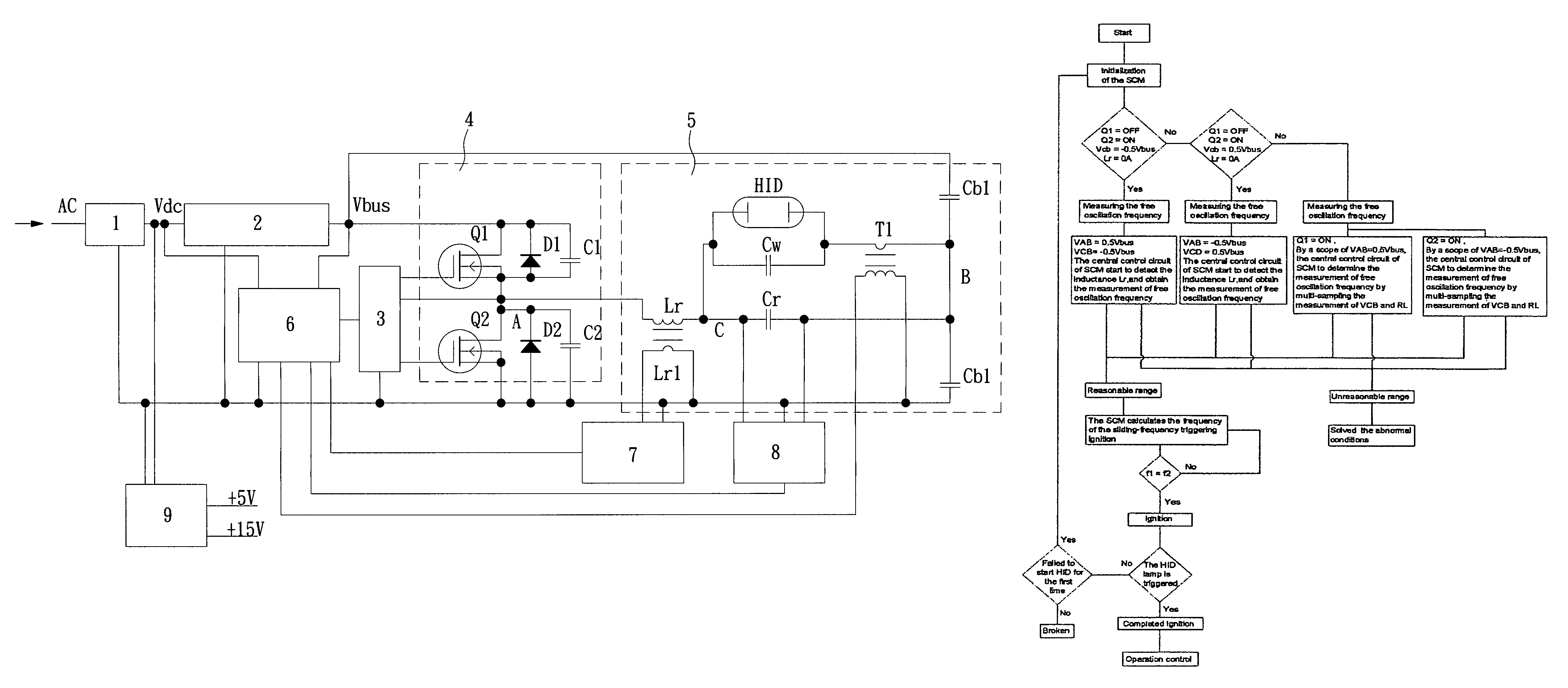
[0025]In order to ensure the accuracy and reliability of the measured free oscillation frequency of the load loop, you can switch off Q1 before executing the abovementioned method for measuring the free oscillation frequency, and switch on Q2 after a break, make sure the time in this state is sufficient enough to make the voltage on capacitor Crw VCB=−0.5Vbus and the current of the of the inductance is basically zero before starting measuring. In this case, under the same condition, it can achieve good repetition of attenuating the free oscillation of the load loop for each time executing this operation, so that accuracy and reliability of the free oscillation frequency of the load loop is ensured.
[0027]In order to ensure the accuracy and reliability of the measured free oscillation frequency of the load loop, you can switch off Q2 before executing the abovementioned method for measuring the free oscillation frequency, and switch on Q1 after a break, make sure the time in this state is sufficient enough to make the voltage on capacitor Crw VCB=0.5Vbus and the current of the of the inductance is basically zero before starting measuring. In this case, under the same condition, it can achieve good repetition of attenuating the free oscillation of the load loop for each time executing this operation, so that accuracy and reliability of the free oscillation frequency of the load loop is ensured.
[0029]In order to ensure the accuracy and reliability of the measured free oscillation frequency of the load loop, you can switch off Q1 and Q4 before executing the abovementioned method for measuring the free oscillation frequency, and switch on Q2 and Q3 after a break, make sure the time in this state is sufficient enough to make the voltage on capacitor Crw VCB=−Vbus and the current of the of the inductance is basically zero before starting measuring. In this case, under the same condition, it can achieve good repetition of attenuating the free oscillation of the load loop for each time executing this operation, so that accuracy and reliability of the free oscillation frequency of the load loop is ensured.
[0031]In order to ensure the accuracy and reliability of the measured free oscillation frequency of the load loop, you can switch off Q2 and Q3 before executing the abovementioned method for measuring the free oscillation frequency, and switch on Q1 and Q4 after a break, make sure the time in this state is sufficient enough to make the voltage on capacitor Crw VCB=Vbus and the current of the of the inductance is basically zero before starting measuring. In this case, under the same condition, it can achieve good repetition of attenuating the free oscillation of the load loop for each time executing this operation, so that accuracy and reliability of the free oscillation frequency of the load loop is ensured.
[0033]For the electronic ballast of HID lamp that adopts half-bridge or full-bridge as the DC / AC switching power driving and generates the high voltage for triggering ignition by making use of the resonance method, this invention adopts the abovementioned technical solution to, before sliding-frequency triggering ignition, timely and accurately measure the free oscillation frequency of the equivalent load loop and based on which to calculate the starting and ending frequency of the sliding-frequency triggering ignition as well as determining the speed or step length of the sliding-frequency, so that to safely and reliably complete the process of the sliding-frequency triggering ignition, to essentially improve the quality and life and other parameters of the electronic ballast of the HID lamp for its wide application in the field of the commercial lighting.

Problems solved by technology

As a result, the sliding-frequency parameter and the free oscillation frequency of this kind of electronic ballast will not match with each other in actual operation, and the power switch of the inverting bridge will endure a hard switch mode with very large current and voltage during the process of sliding-frequency ignition, which may cause damage of the inverting bridge power switch.
This is an important reason why this kind of electronic ballast of the HID lamp is likely to be damaged during ignition and is not popularized until now.
As a matter of fact, however, when K>4, due to the switching and conducting wastage of Q1 and Q2, as well as the wastage of the load loop itself, it accelerates attenuation of the loop current and weakens the resonant features gradually, until not sufficient to generate the high voltage for triggering ignition, so it is not adopted generally.

Method used


Image

  • Adaptive sliding-frequency triggering ignition process for electronic ballast of high pressure gas discharge lamp
  • Adaptive sliding-frequency triggering ignition process for electronic ballast of high pressure gas discharge lamp
  • Adaptive sliding-frequency triggering ignition process for electronic ballast of high pressure gas discharge lamp

Examples


Embodiment Construction

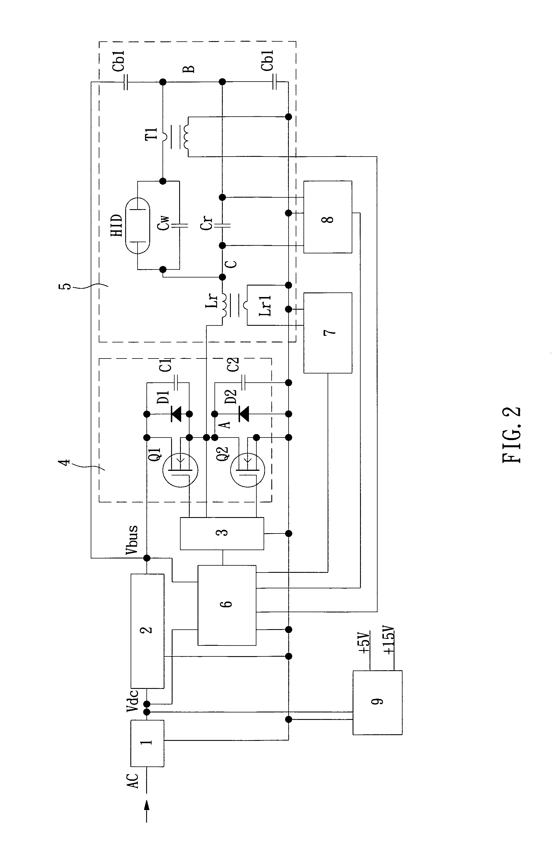
[0038]The circuit of this invention consists of the electronic ballast of HID lamp that includes all basic functional models, and adopts half-bridge or full-bridge DC / AC as power output. The functional models include:

[0039]Rectifying circuit (1): after inputting AC rectification, outputting impulse DC voltage Vdc to Power factor correcting circuit (2);

[0040]Power factor correcting circuit (2): making input power factor reach 1 and providing DC working voltage Vbus to inverting power output circuit (4);

[0041]Driving circuit (3): receiving control signal from the single-chip central controlling circuit (6) and sending switch control signal to inverting power output circuit (4);

[0042]Inverting power output circuit (4): as for half-bridge DC / AC power output, the components include inverting switch Q1 and Q2, freewheeling diode D1 and D2, buffering capacitor C1 and C2, receiving the switch control signal sent by driving circuit (3) and sending square wave driving signal to load circuit (...


PUM


Abstract

An adaptive sliding-frequency triggering ignition method for electronic ballast of high pressure gas discharge lamp includes the steps of: measuring an accurate value of free oscillation frequency of the ballast load loop by using a single-chip before sliding-frequency triggering ignition, implementing safe and reliable sliding-frequency triggering ignition after calculating the initial frequency and ending frequency of sliding-frequency triggering ignition according to the accurate value. The method can safely and reliably finish sliding-frequency triggering ignition course, thus improving the parameters such as the quality, life of the high pressure gas discharge lamp electronic ballast.

Description

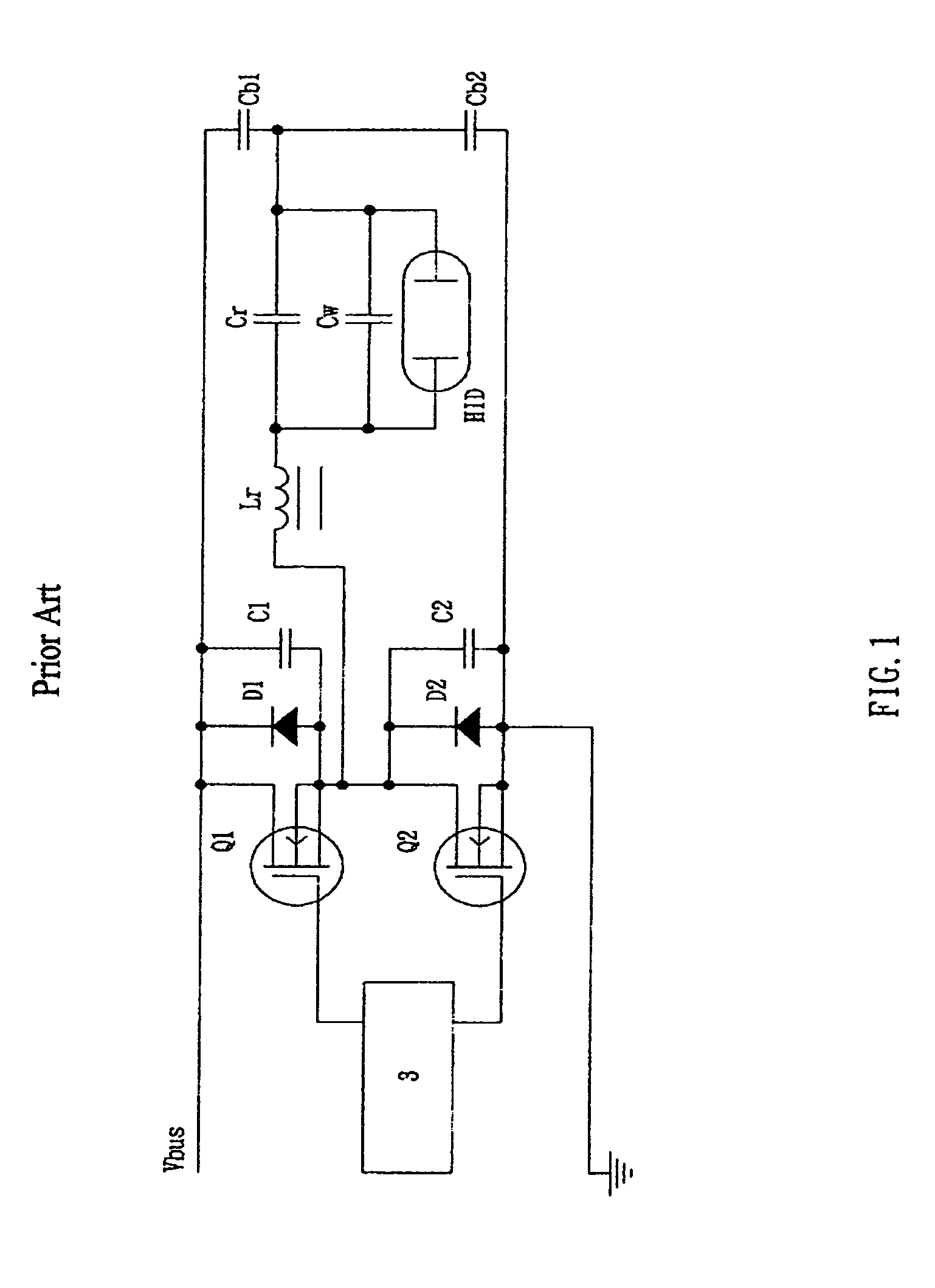
FIELD OF THE INVENTION[0001]This invention is an adaptive sliding-frequency triggering ignition method for electronic ballast of high pressure gas discharge lamp.DESCRIPTION OF PRIOR ART[0002]High pressure gas discharge lamps (hereinafter referred to as HID lamp) usually require a more than 2500V high pressure triggering ignition impulse to allow the ionization of the tube breaking into the arc and discharging. To adopt half-bridge or full-bridge as the power drive of the DC / AC switch, the work frequency is between tens of KHz to hundred of KHz; the HID lamp is a HID lamp electronic ballast that connects to inverting bright through LC matching network, and at present, the LC series resonance method which has lower cost is usually adopted to trigger the high pressure for ignition. Refer to FIG. 1, the traditional method is that, the inverting bridge generates a starting driving square wave whose frequency is determined during designing or production, and then reduces the frequency at...

Claims


Application Information

Patent Timeline
Patent Type & Authority Patents(United States)
IPC IPC(8): G05F1/00
CPCH05B41/2881Y02B20/204H05B41/382Y02B20/00
Inventor HE, ZHENG
Owner FOSHAN METROPOLIS LIGHTING
Learn More