Driving force distribution device
a technology of driving force and distribution device, which is applied in the direction of mechanical actuated clutches, interengaging clutches, gearing, etc., can solve the problems of unnecessary weight increase, unnecessarily large torque directed to the auxiliary driving wheels,
- Summary
- Abstract
- Description
- Claims
- Application Information
AI Technical Summary
Benefits of technology
Problems solved by technology
Method used
Image

Examples
first embodiment
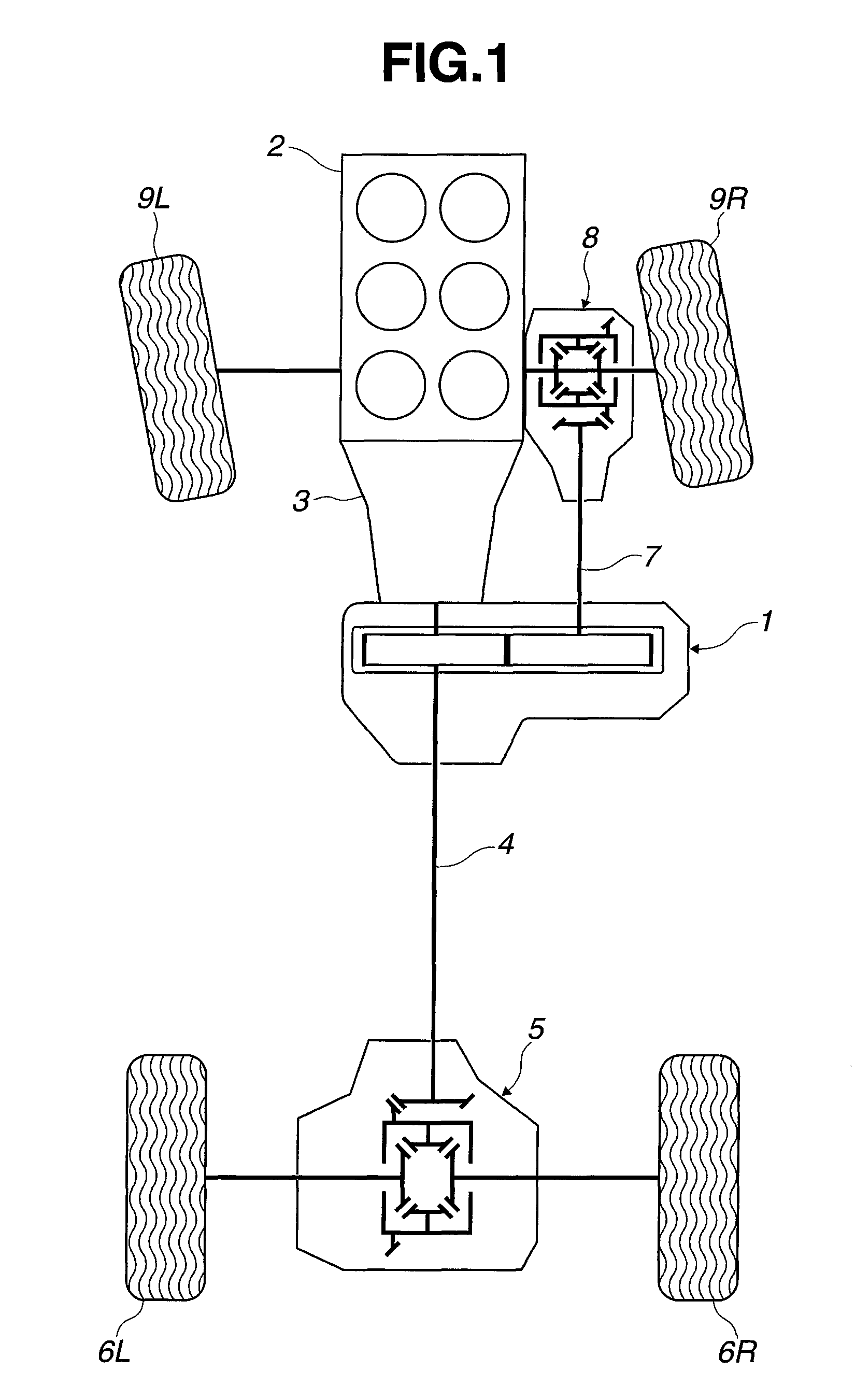
[0023]FIG. 1 is a schematic plan view from above a four wheel drive vehicle, showing a powertrain of the four wheel drive vehicle which is provided with a driving force distribution device 1 according to the present invention. The four wheel drive vehicle of FIG. 1 is based on a rear wheel drive vehicle in which rotation from an engine 2 is shifted by a transmission 3, and then transmitted through a rear propeller shaft 4 and a rear final drive unit 5 to left and right rear wheels 6L, 6R, and constructed so that a part of torque to left and right rear wheels (main driving wheels) 6L, 6R is transmitted by driving force distribution device 1 through a front propeller shaft 7 and a front final drive unit 8 to left and right front wheels (auxiliary driving wheels) 9L, 9R, thus achieving four wheel driving.
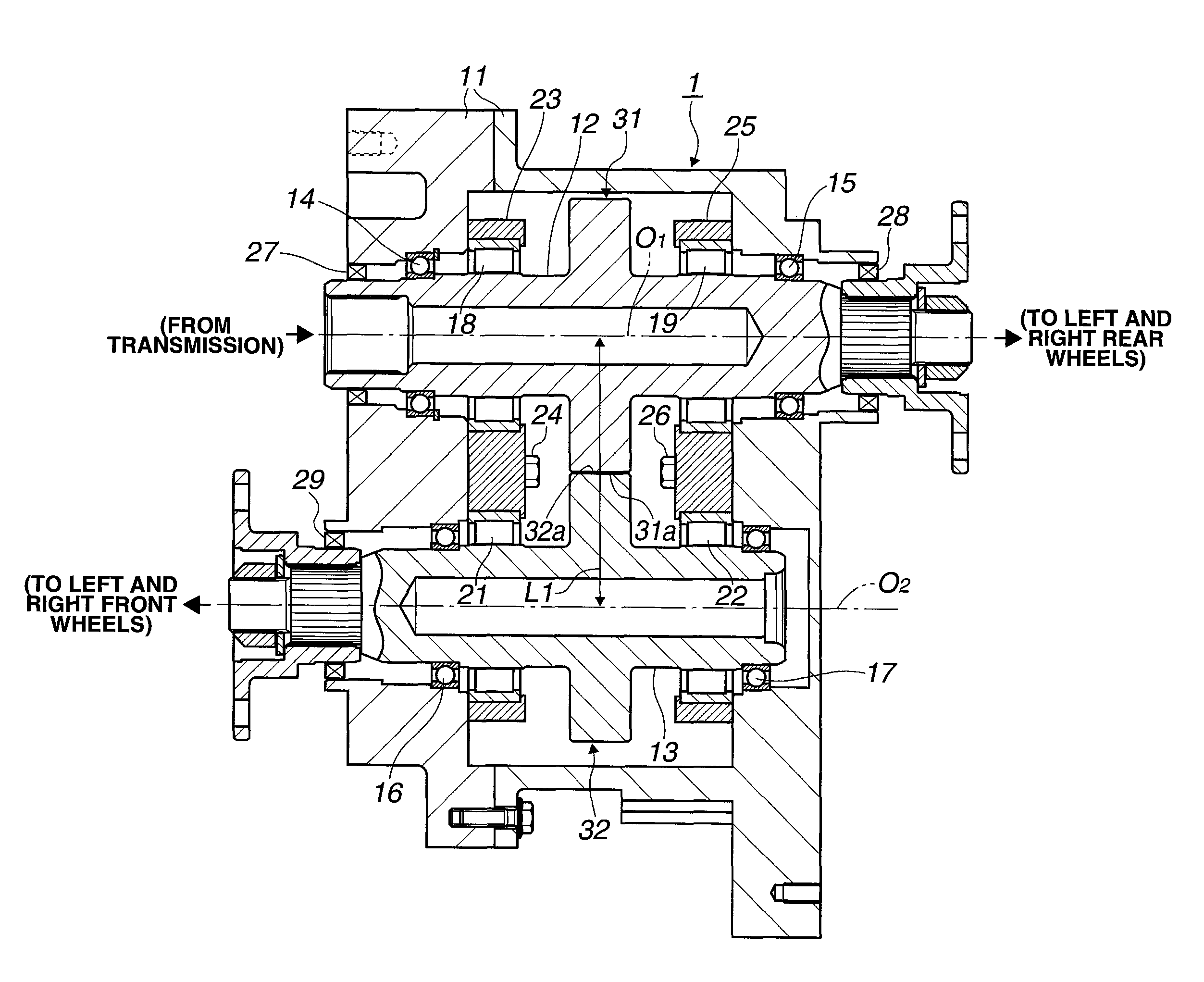
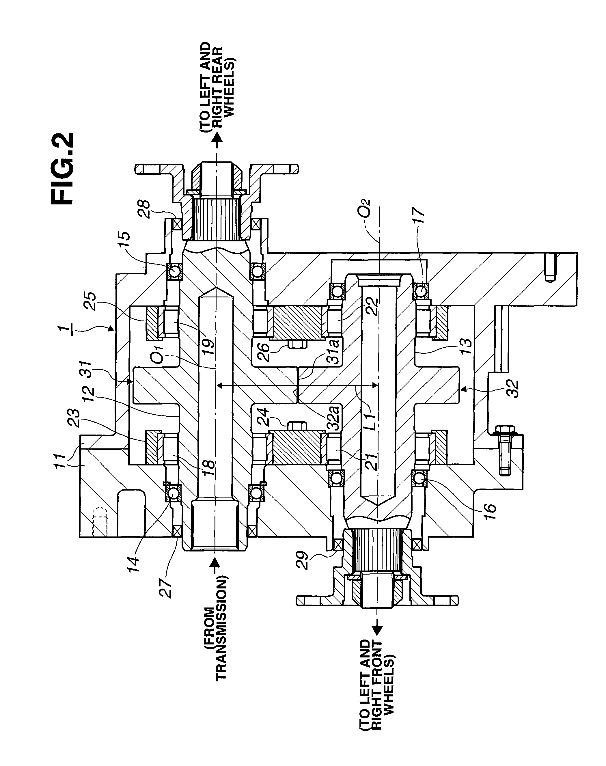
[0024]Driving force distribution device 1 is thus configured to set torque distribution between left and right rear wheels (main driving wheels) 6L, 6R, and left and right front wheels...
second embodiment
[0043]FIG. 3 shows the present invention in which driving force distribution device 1 is configured so that the inter-roller-axis distance L1 between first roller 31 and second roller 32 is arbitrarily set so as to arbitrarily set the radial pressing force between first roller 31 and second roller 32. For this purpose, output shaft 13 is shortened as compared to the embodiment shown in FIG. 2, and rotatably supported with respect to housing 11 only by ball bearing 16 and roller bearing 21 which are similar to those in FIG. 2.
[0044]In FIG. 3, the left end of output shaft 13 which extends out of housing 11 is coupled to front final drive unit 8 through front propeller shaft 7, as in the embodiment described above. In FIG. 3, a crankshaft 41 is arranged to face the right end (inside end) of output shaft 13 which is located in housing 11.
[0045]The left end (in FIG. 3) of crankshaft 41 is fitted to the inside end of output shaft 13 though a needle bearing 42 so that the left end (in FIG....
third embodiment
[0079][Third Embodiment]FIG. 5 shows the present invention, in which the crankshaft 41 according to the second embodiment in the form of a solid inner shaft is replaced with crankshafts 51L, 51R in the form of a pair of hollow outer shafts, and the radial displacement of second roller 32 is caused by rotational displacement of crankshafts 51L, 51R, to change the inter-roller-axis distance L1 between first roller 31 and second roller 32.
[0080]Accordingly, second roller 32 is formed integrally with output shaft 13, and the hollow crankshafts 51L, 51R are located at both axial ends of second roller 32. Both ends of output shaft 13, which project from both axial ends of second roller 32, are fitted in central holes 51La, 51Ra (semidiameter Ri) of crankshafts 51L, 51R. Bearings 52L, 52R are disposed in the fitting portions so that output shaft 13 is supported in the central holes 51La, 51Ra of crankshafts 51L, 51R for free rotation about the central axis O2 of the central holes 51La, 51R...
PUM
 Abstract
Description
Claims
Application Information
 - R&D
- Intellectual Property
- Life Sciences
- Materials
- Tech Scout
- Unparalleled Data Quality
- Higher Quality Content
- 60% Fewer Hallucinations
Browse by: Latest US Patents, China's latest patents, Technical Efficacy Thesaurus, Application Domain, Technology Topic, Popular Technical Reports.
© 2025 PatSnap. All rights reserved.Legal|Privacy policy|Modern Slavery Act Transparency Statement|Sitemap|About US| Contact US: help@patsnap.com