Pneumatic radial tire

a radial tire and pneumatic technology, applied in the direction of yarn, non-skid devices, transportation and packaging, etc., can solve the problems of increasing the rolling resistance of the pneumatic radial tire, increasing the orientation of the metallic structure of the single steel wire, and increasing the diameter of the steel cord composed of a plurality of intertwined filaments. to achieve the effect of improving the durability of the tir

Active Publication Date: 2014-09-02
THE YOKOHAMA RUBBER CO LTD
View PDF21 Cites 2 Cited by
  • Summary
  • Abstract
  • Description
  • Claims
  • Application Information

AI Technical Summary

Benefits of technology

[0005]An object of the present invention is to provide a pneumatic radial tire that uses a belt layer including a plurality of single steel wires aligned and embedded in rubber, wherein the pneumatic radial tire is able to demonstrate improved tire durability.
[0028]Tire durability can be improved according to the pneumatic tire of the present invention.

Problems solved by technology

However, the cord diameter of the steel cords composed of a plurality of intertwined filaments grows larger due to internal gaps formed in between the filaments.
Accordingly, since a large amount of coating rubber is required, the rolling resistance of the pneumatic radial tire easily increases due to energy loss of the coating rubber.
However, an excessive orientation in the metallic structure of the single steel wire increases in correspondence with the wire surface being closer to the wire drawing die surface in a single steel wire subjected to wire drawing.
As a result, there is a problem in that the fatigue resistance of the single steel wire deteriorates and the tire durability is reduced when single steel wires are used as-is after the wire drawing as reinforcing cords in the belt layer.

Method used


Image

  • Pneumatic radial tire
  • Pneumatic radial tire
  • Pneumatic radial tire

Examples


first embodiment

Pneumatic Radial Tire

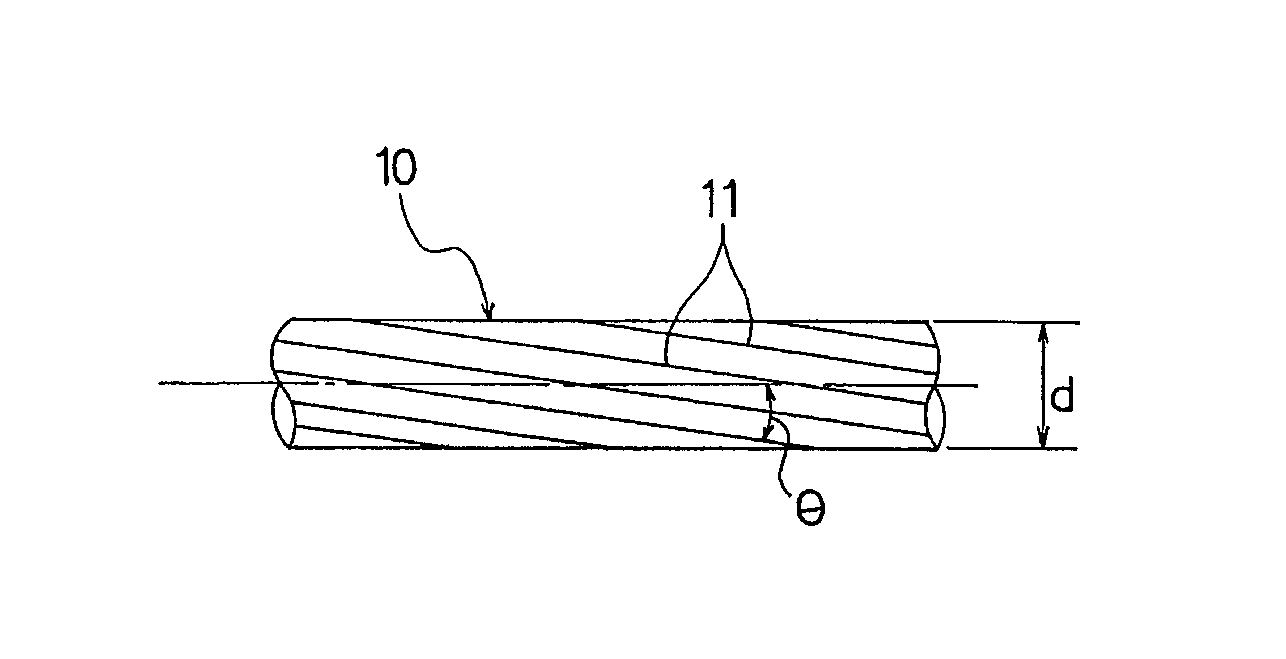
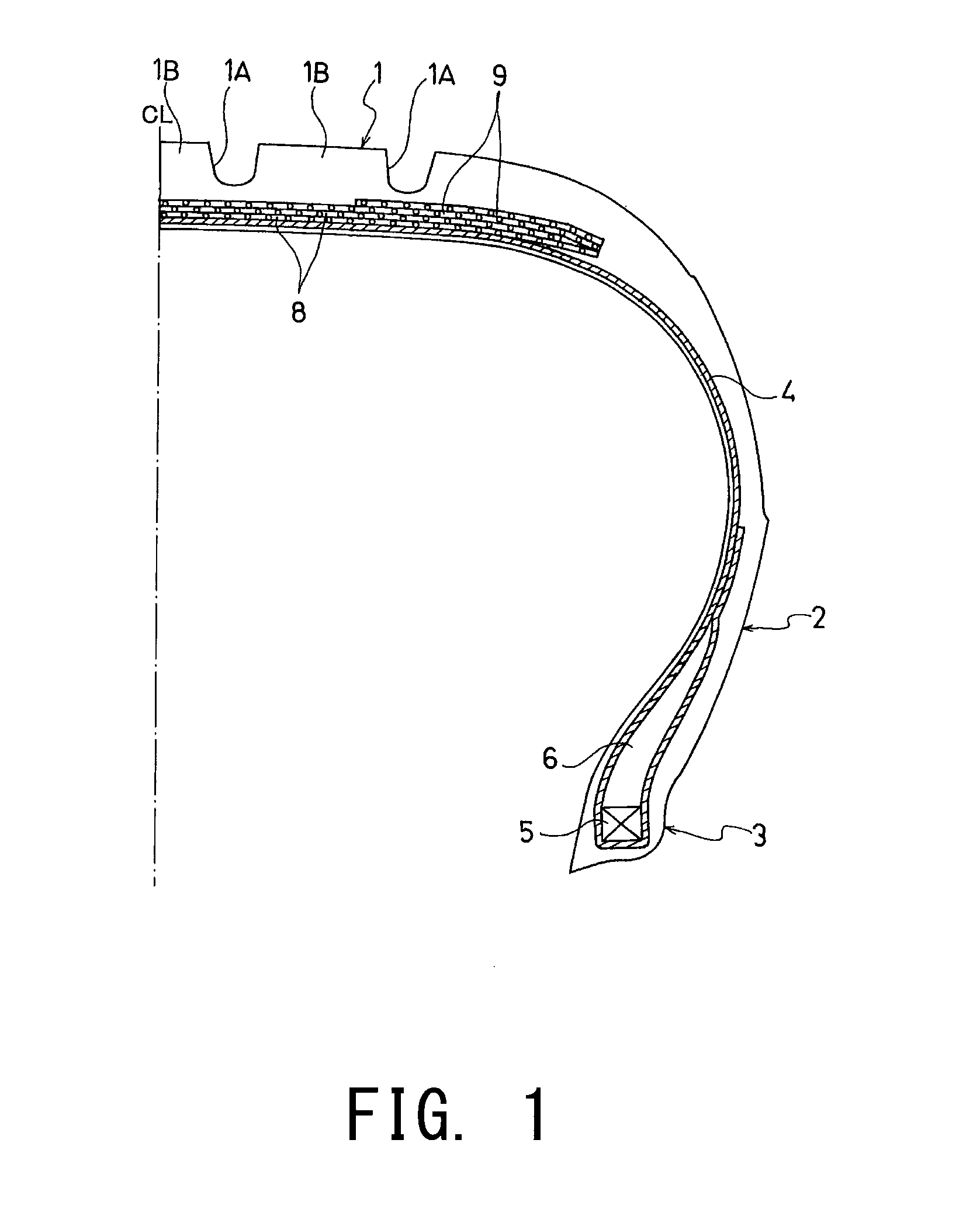
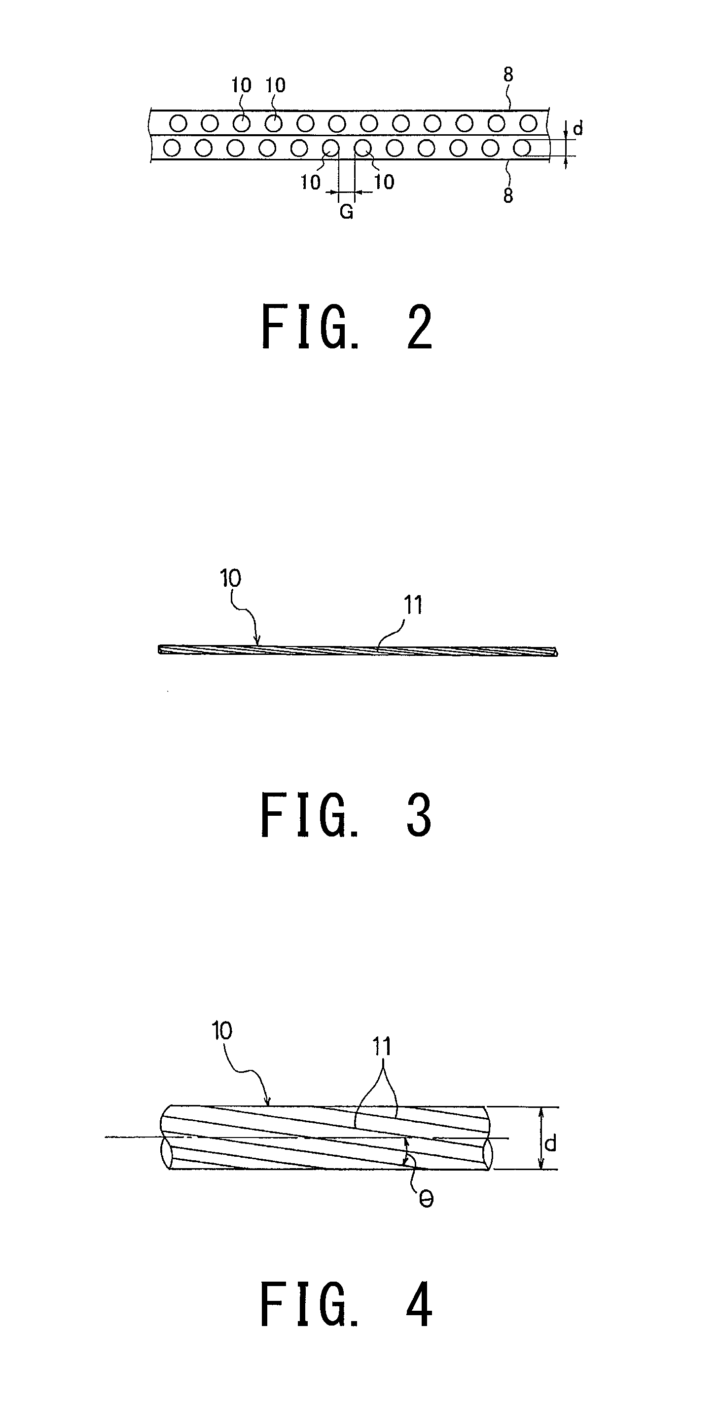
[0039]As a result of diligent research on pneumatic radial tires including belt layers including a plurality of single steel wires aligned and embedded in rubber, the present inventor found that tire durability is noticeably improved by optimizing the wire diameter and the average interval of single steel wires provided with axial torsion and by suitably assuring the out-of-plane bending stiffness of the tread portion that envelops the belt layers to suppress buckling of the tread portion. The inventor found that the tire durability can be further improved by setting the implanted density E (wires / 50 mm) of the single steel wires to a certain value or higher to suitably assure the out-of-plane bending stiffness of the tread portion that envelops the belt layers to suppress buckling of the tread portion. The present inventor made the present invention based on these findings.

[0040]FIG. 1 shows a passenger vehicle pneumatic radial tire that is a first embodiment o...

second embodiment

Pneumatic Radial Tire

[0067]The passenger vehicle pneumatic radial tire that is the second embodiment has the structure shown in FIG. 1 in the same way as the passenger vehicle pneumatic radial tire that is the first embodiment.

[0068]A difference between the structure of pneumatic radial tire of the second embodiment and that of the pneumatic radial tire of the first embodiment is that whereas the out-of-plane bending stiffness is not less than 6000 N·mm2 per inch of length of the tread portion in the circumferential direction when the point where the force is applied is located at the circumferential groove in the first embodiment, the implanted density E (wires / 50 mm) of the single steel wires 10 in the second embodiment satisfies E≧1869×d2−1838×d+493, where d is the wire diameter. Other than the above, the structure of the pneumatic radial tire of the second embodiment is the same as the structure of the pneumatic radial tire of the first embodiment. Specifically, in the pneumatic...

working examples

[0079]Pneumatic radial tires with the tire size of 195 / 65R15 were manufactured. The manufactured pneumatic radial tires include two belt layers 8 including the plurality of single steel wires 10 aligned with each other and embedded in rubber, the belt layers 8 disposed on the outside in the tire radial direction of the carcass layer at the tread portion, and the belt cover layer 9 provided on the outside in the tire radial direction of the belt layers 8. Tire 1 to tire 15 were manufactured having the wire diameter d, the helix angle θ of the axial torsion on a surface of the wire, the implanted density E, and the average interval G of the single steel wires 19 of the belt layer 8, the out-of-plane bending stiffness per one inch in length of the tread portion in the circumferential direction where the force application point is located at the circumferential groove, and the maximum value of the thickness of the tread portion, the minimum value of the thickness of the tread portion, a...


PUM

PropertyMeasurementUnit
diametersaaaaaaaaaa
helix angleaaaaaaaaaa
lengthaaaaaaaaaa

Abstract

Each of belt layers of a pneumatic radial tire includes a plurality of single steel wires with an identical wire diameter extending linearly in an identical direction in alignment with each other and embedded in rubber. Each of the wires is provided with axial torsion. On the outer surface of a tread portion, circumferential grooves extend in the circumferential direction of the tire. The wire diameters of the single steel wires are 0.28 mm to 0.38 mm. An average of intervals of the single steel wires is not less than 0.10 mm. The tire has an out-of-plane bending stiffness of not less than 6000 N·mm2 per inch of length of the tread portion in the circumferential direction when a force application point is located at the circumferential groove. The implanted density E (wires / 50 mm) of the single steel wires satisfies E≧1869×d2−1838×d+493, where d is the wire diameter.

Description

CROSS-REFERENCE TO RELATED APPLICATIONS[0001]This U.S. National stage application claims priority under 35 U.S.C. §119(a) to Japanese Patent Application No. 2011-135381, filed in Japan on Jun. 17, 2011, and to Japanese Patent Application No. 2011-135383, filed in Japan on Jun. 17, 2011, the entire contents of Japanese Patent Application Nos. 2011-135381 and 2011-135383 are hereby incorporated herein by reference.FIELD OF THE INVENTION[0002]The present invention relates to a pneumatic radial tire.DESCRIPTION OF THE RELATED ART[0003]Conventionally, steel cords composed of a plurality of intertwined filaments are used as reinforcing cords for a belt layer in a pneumatic radial tire (hereinbelow also referred to as a “tire”). However, the cord diameter of the steel cords composed of a plurality of intertwined filaments grows larger due to internal gaps formed in between the filaments. Accordingly, since a large amount of coating rubber is required, the rolling resistance of the pneumati...

Claims


Application Information

Patent Timeline
Patent Type & Authority Patents(United States)
IPC IPC(8): B60C9/22B60C9/00B60C9/18B60C9/20
CPCB60C9/0007B60C9/0064B60C9/18B60C9/2006B60C9/22B60C2009/2074B60C2009/2077B60C2009/2048B60C2009/2083Y10T152/10801Y10T152/10765
Inventor UEDA, YOSHIOKANEHIRA, YOSHIKI
Owner THE YOKOHAMA RUBBER CO LTD
Why Eureka
Try Eureka