X-ray tubes

a technology of x-ray tubes and x-ray tubes, which is applied in the manufacture of x-ray tubes, electrode systems, electric discharge tubes/lamps, etc., can solve the problems of extremely high assembly costs, and achieve the effect of quick and efficien

Active Publication Date: 2014-09-02
RAPISCAN SYST INC (US)
View PDF246 Cites 15 Cited by
  • Summary
  • Abstract
  • Description
  • Claims
  • Application Information

AI Technical Summary

Benefits of technology

[0006]The housing sections may be formed by pressing. This makes the method quick and efficient. Various features of the housing, such as welding formations or mounting apertures for feed-throughs, may be formed by stamping. This can be done simultaneously and on the same press tool as the formation of the main housing sections, or may be done as a separate step.

Problems solved by technology

Such assemblies are extremely expensive to put together since they require precision machining to meet stringent vacuum requirements.

Method used


Image

  • X-ray tubes
  • X-ray tubes
  • X-ray tubes

Examples


Embodiment Construction

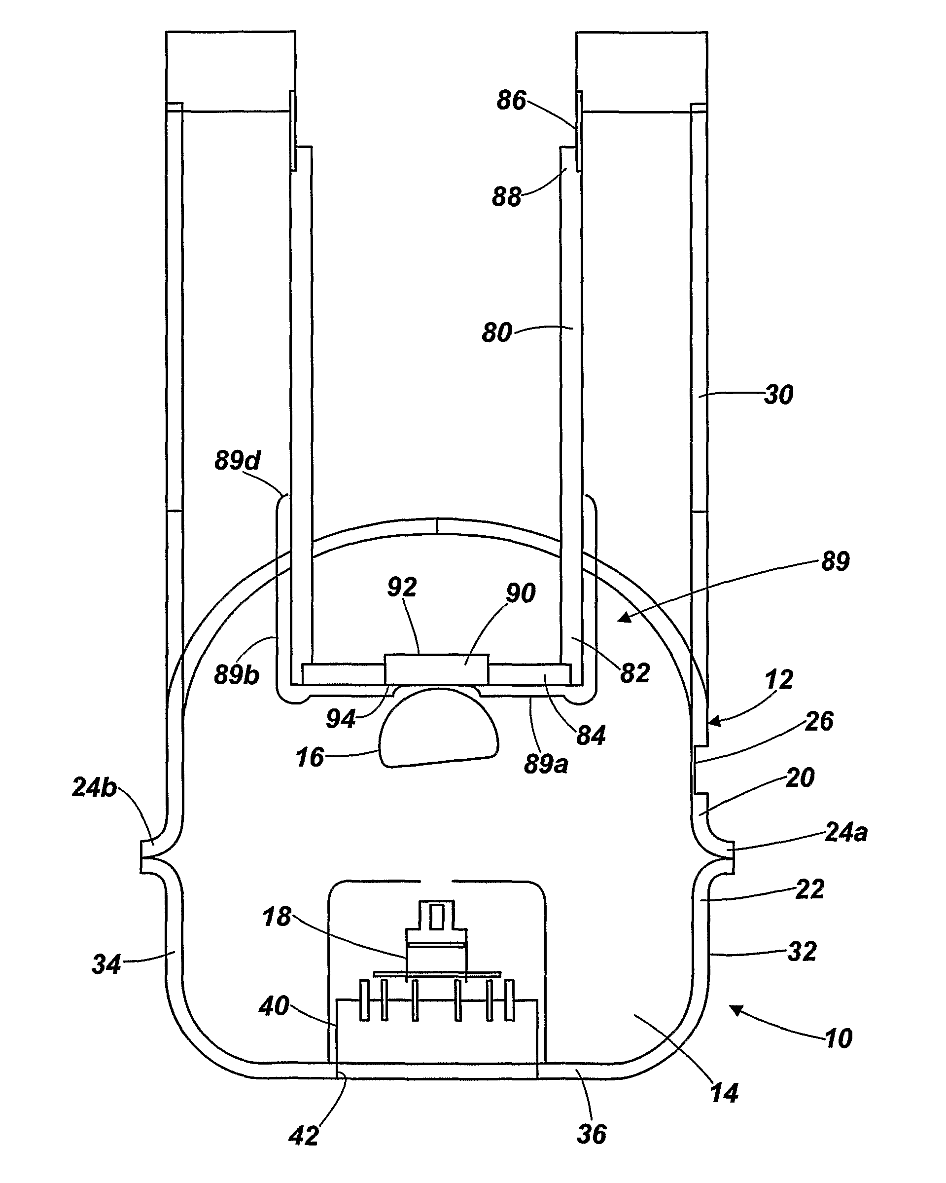
[0021]Referring to FIG. 1, an X-ray tube 10 comprises a housing 12 which defines a vacuum chamber 14, with a hollow tubular anode 16 and a series of electron sources or guns 18 supported inside the vacuum chamber 14. In this embodiment the vacuum chamber is in the shape of a torus arranged to extend around a scanning volume, but other shapes can be used as appropriate for different applications.

[0022]The housing 12 is formed in two sections: an anode section 20 and a cathode section 22. The anode section 20 is approximately semi-circular or C-shaped in section with weld rims 24a, 24b formed at its radially inner and outer edges. The anode 16 is supported on the anode section 20 by means of an anode feed-through 30 which is formed separately from the housing 10 and welded onto it, as will be described in more detail below, and a number of mountings which are similar to the feed-through 30 but do not include the electrical connections of the feed-through, being for physical support on...


PUM

PropertyMeasurementUnit
currentaaaaaaaaaa
lengthaaaaaaaaaa
thicknessaaaaaaaaaa

Abstract

An X-ray tube is produced by forming a first housing section 20 from sheet metal; forming a second housing section 22 from sheet metal, mounting an electron source 18 in one of the housing sections; mounting an anode 16 in one of the housing sections; and joining the housing sections 20, 22 together to form a housing defining a chamber with the electron source 18 and the anode 16 therein.

Description

CROSS-REFERENCE TO RELATED APPLICATIONS[0001]The present application is a national stage application of PCT / GB2009 / 051178, filed on Sep. 13, 2008. The present application further relies on Great Britain Patent Application Number 0816823.9, filed on Sep. 11, 2009, for priority. Both priority applications are herein incorporated by reference in their entirety.FIELD OF THE INVENTION[0002]The present invention relates to X-ray tubes and in particular to multi-focus X-rays tubes for imaging applications.BACKGROUND OF THE INVENTION[0003]Multi-focus X-ray tubes generally comprise a single anode in linear or arcuate geometry which can be irradiated along its length by two or more switched electron sources. In a typically configuration, hundreds of electron sources or guns might be used to irradiate a single anode with a length of over 1 m. Often the electron guns will be actuated individually and sequentially in order to create a rapidly moving X-ray beam. Alternatively, the electron source...

Claims


Application Information

Patent Timeline
Patent Type & Authority Patents(United States)
IPC IPC(8): H01J35/10H01J35/12H01J35/16
CPCH01J35/16H01J35/165H01J35/12Y10T29/49002H01J9/125H01J2209/18H01J9/244H01J9/36H01J35/13
Inventor MORTON, EDWARD, JAMES
Owner RAPISCAN SYST INC (US)
Why Eureka
Try Eureka