
Matrix decomposition using dataflow techniques

a dataflow and matrix technology, applied in the field of cholesky decomposition in integrated circuit devices, can solve the problems of increasing inefficiency, imposing noticeable latency, and various limitations in implementation

Active Publication Date: 2014-09-02
ALTERA CORP
View PDF4 Cites 7 Cited by
  • Summary
  • Abstract
  • Description
  • Claims
  • Application Information

AI Technical Summary

Benefits of technology

The present invention is about efficient and flexible circuitry for implementing Cholesky decomposition. The invention includes matrix operation circuitry for performing matrix decomposition operable to triangulate an input matrix to create a triangulated resultant matrix. The circuitry includes a register structure for storing partial sums of products associated with a row of the triangulated resultant matrix and an accumulator for combining the partial sums. The dataflow controller selectively outputs data associated with either the accumulator or the second register structure for generating an additional element of the triangulated resultant matrix. The invention also includes a controller for generating a triangulated matrix with column, bank, and row counter circuitsry for activating the appropriate control circuitry. The technical effect of the invention is to provide a flexible and efficient tool for performing Cholesky decomposition to create triangulated matrices.

Problems solved by technology

Similarly, the square root calculation in the computation of Li,j can also impose noticeable latency.
Such implementations have various limitations.
For example, these implementations limit the use of important resources such as the adder tree to a fraction of the operation time only, which increases inefficiency.
Moreover, these standard implementations suffer from significant latency, especially when manipulating floating point data types.
Such long latencies may cause significant routing congestion and render dataflow management intractable.
Another limitation of the standard implementations is the need to know the maximum number of items to be combined at creation time, which reduces the run-time flexibility and increases the state-machine complexity of the design.
Because of these limitations, standard implementations may result in systems with poor performance levels, especially with floating point operations.

Method used


Image

  • Matrix decomposition using dataflow techniques
  • Matrix decomposition using dataflow techniques
  • Matrix decomposition using dataflow techniques

Examples


Embodiment Construction

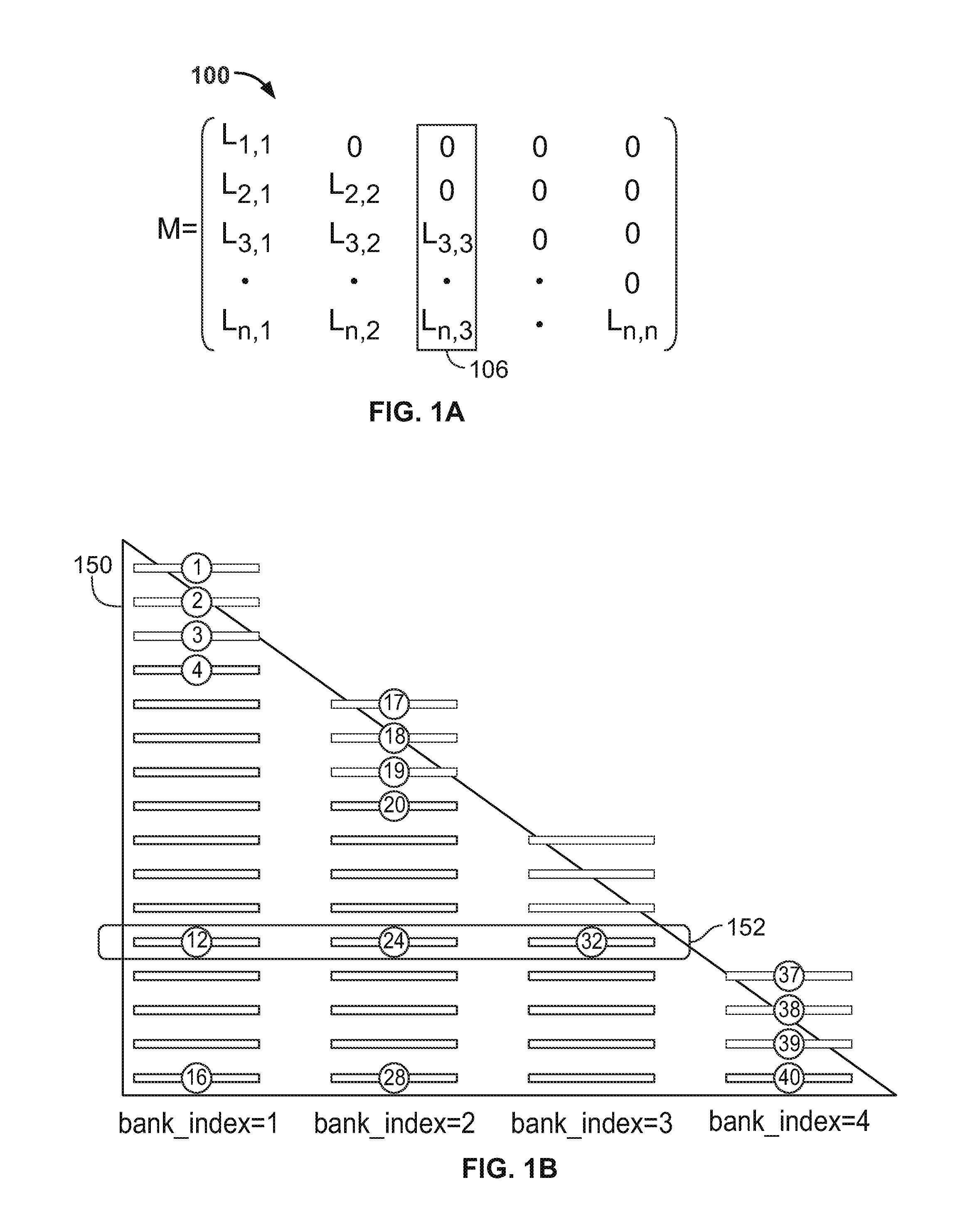
[0023]An example 100 of a triangulated n-by-n matrix M resulting from a Cholesky decomposition is shown in FIG. 1. The elements on the diagonal are L1,1, . . . , Ln,n. In each jth column (e.g., column 106), the elements under Lj,j are Li,j, i=j+1, . . . , Ln,j. The matrix may be considered to be empty above the diagonal, or the elements above the diagonal may be considered to be zeroes, as illustrated in example 100. The elements on the diagonal are L1,1, . . . , Ln,n and can be obtained using the following equation:

[0024]Li,i=(ai,i-∑k=1i-1⁢Li,k·Li,k)(EQ.⁢1)

where ai,i is the i,ith element of the original input matrix A, and Li,k is the i,kth element in the resultant triangulated matrix M. The subsequent elements in the jth column of M may be calculated as:

[0025]Li,j=1Lj,j⁢(ai,j-∑k=1j-1⁢Li,k⁣·Lj,k),for⁢⁢i>j(EQ.⁢2)

[0026]In one sequential approach, elements of the resultant matrix may be computed sequentially in order, e.g., from the first column to the last column and from the first r...


PUM


Abstract

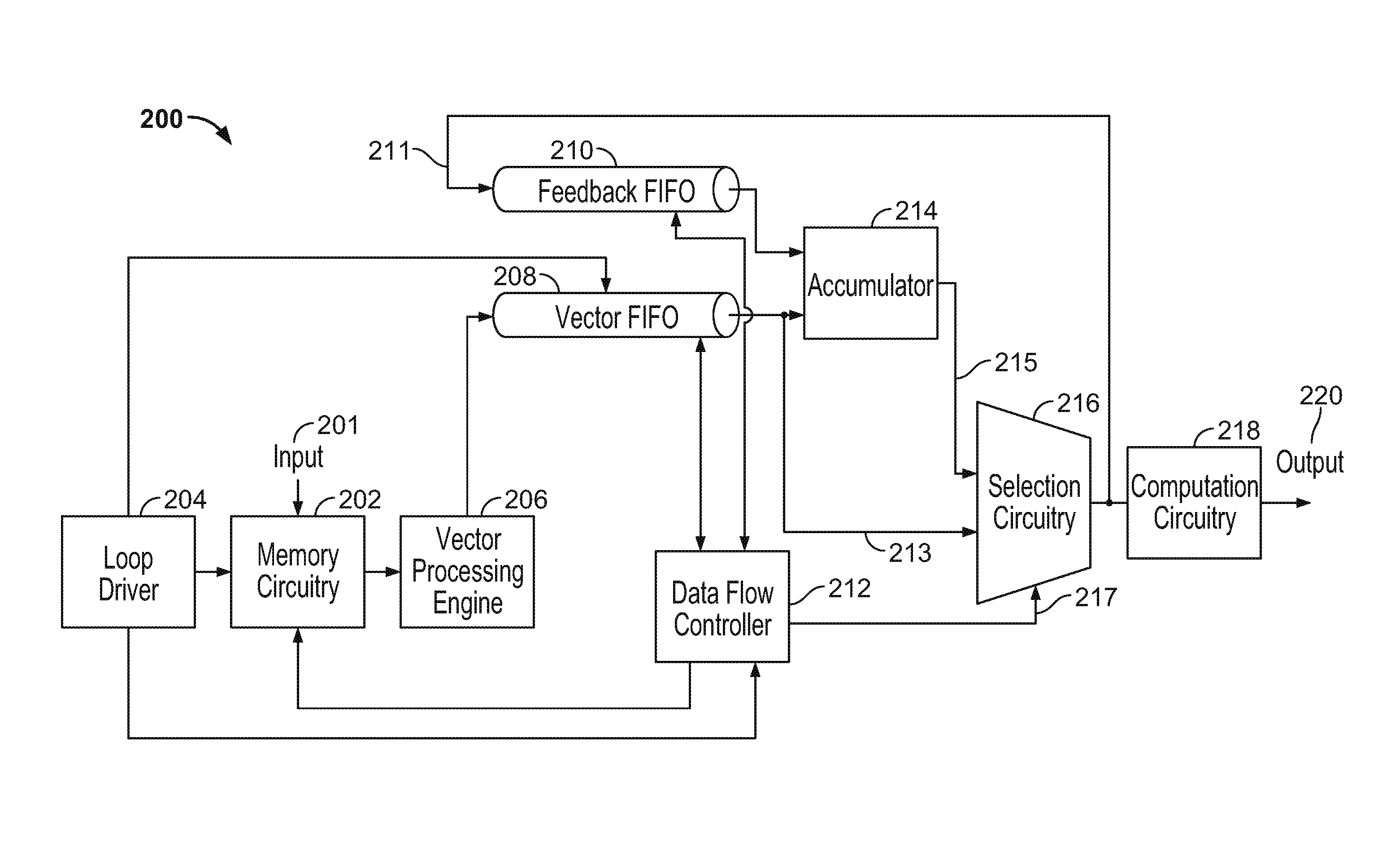
Efficient and scalable circuitry for performing Cholesky decomposition is based on a dataflow style architecture which uses self-timed circuitry and eliminates the need for complicated state machines. Calculations are ordered such that partial sums of products are created in parallel subject to data dependency requirements, allowing a single accumulator to perform the summation. A Vector FIFO receives a partial sum of products from a vector processing engine. A Feedback FIFO stores partial results and feeds the partial results back to the data path based on signals from a dataflow controller. The circuitry is flexible to allow different matrix sizes, speed grades, and target frequencies without recompilation.

Description

FIELD OF THE INVENTION[0001]This invention relates to performing Cholesky decomposition in integrated circuit devices, and particularly in programmable integrated circuit devices such as programmable logic devices (PLDs).BACKGROUND OF THE INVENTION[0002]Certain matrix operations require that a matrix be factored. For example, factoring a matrix may be necessary when a matrix is to be inverted. The result may be a “triangulated” matrix—i.e., a matrix with zero values above the diagonal. The consequence is that only the values on the diagonal, and in the columns below those values, need to be calculated.[0003]In Cholesky decomposition, to factor an input matrix A, an element Li,i of the diagonal of the resultant triangulated matrix M, may be calculated as:[0004]Li,i⁢(ai,i-∑k=1i-1⁢Li,k·Li,k)where ai,i is the i,ith element of the original input matrix A, and Li,k is the i,kth element in the resultant triangulated matrix M. The subsequent elements in the jth column of M may be calculated...

Claims


Application Information

Patent Timeline
IPC IPC(8): G06F17/16
CPCG06F17/16
Inventor PERRY, STEVENCHEUNG, COLEMAN C.
Owner ALTERA CORP
Learn More