

Seat back frame for vehicle seat
a vehicle seat and seat back technology, applied in the direction of chairs, pedestrian/occupant safety arrangements, vehicular safety arrangements, etc., can solve the problems of increasing the size of the seat, achieve the effect of effectively protecting the reducing the head height of the occupant, and reducing the impact of the head or neck of the occupan
- Summary
- Abstract
- Description
- Claims
- Application Information
AI Technical Summary
Benefits of technology
Problems solved by technology
Method used
Image

Examples
first embodiment
(1) First Embodiment
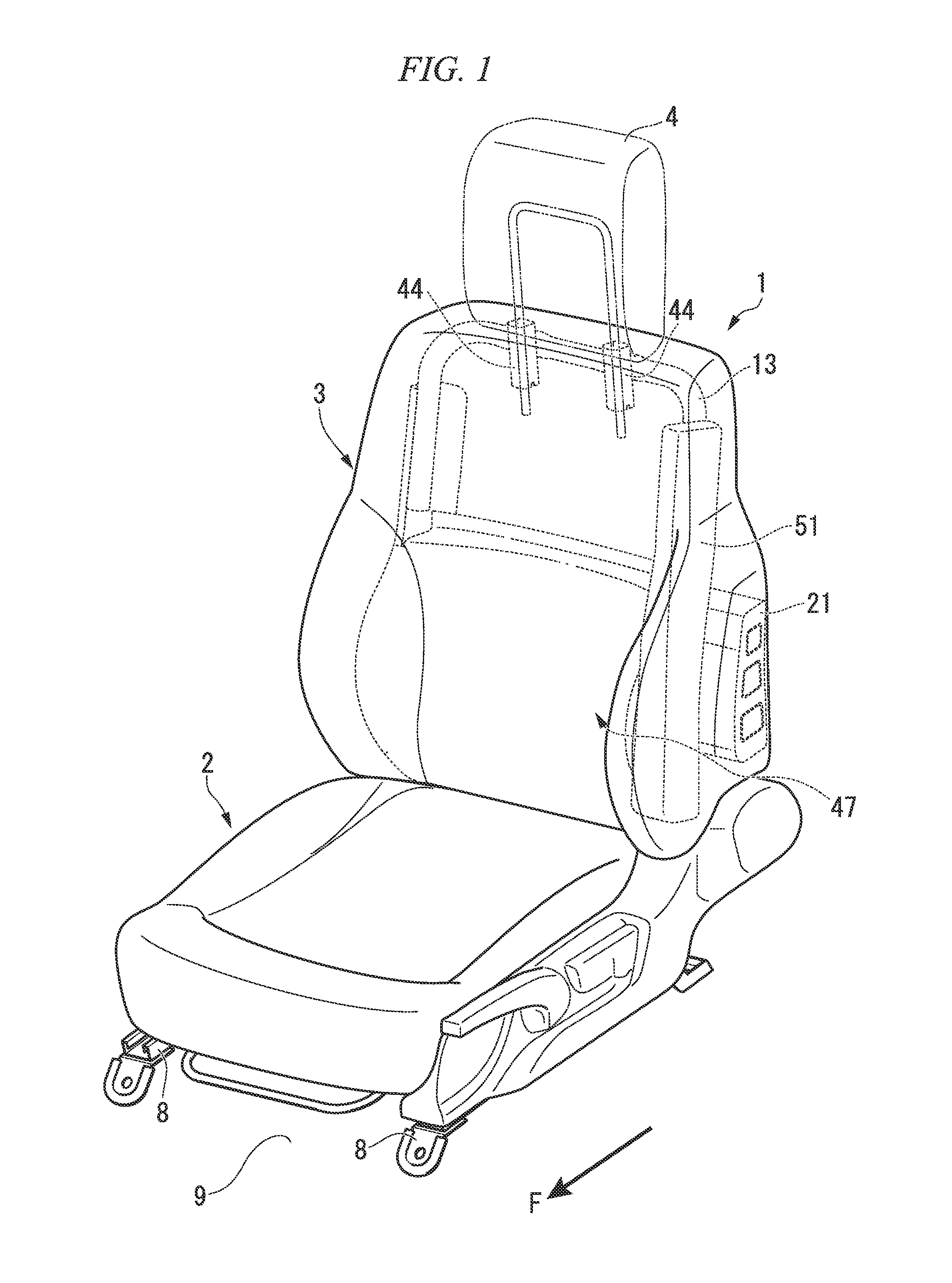
[0069]Hereinafter, a vehicle seat according to a first embodiment of the present invention will be described with reference to FIGS. 1 to 6. In addition, in drawings, an arrow F denotes the front side of the vehicle.
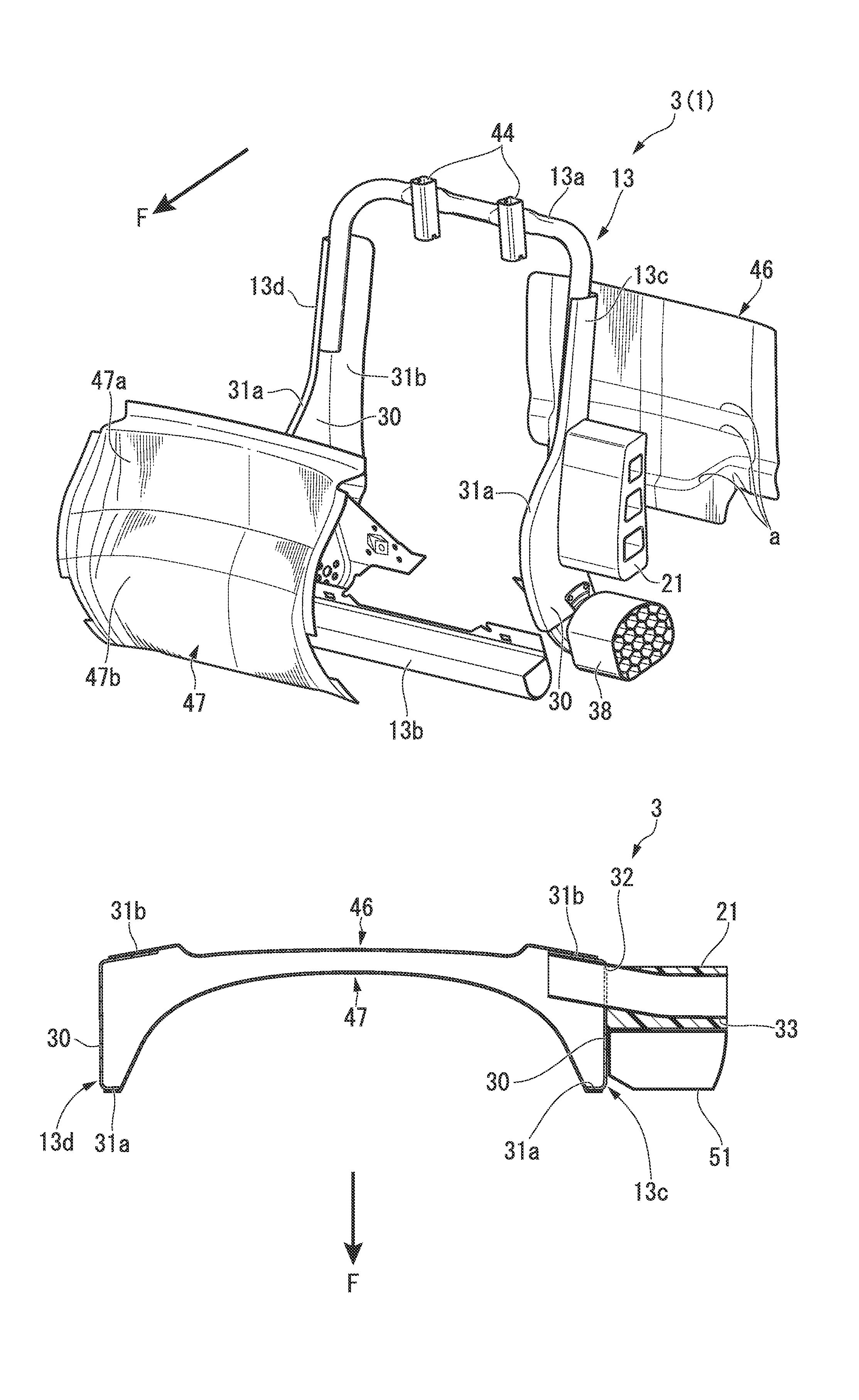
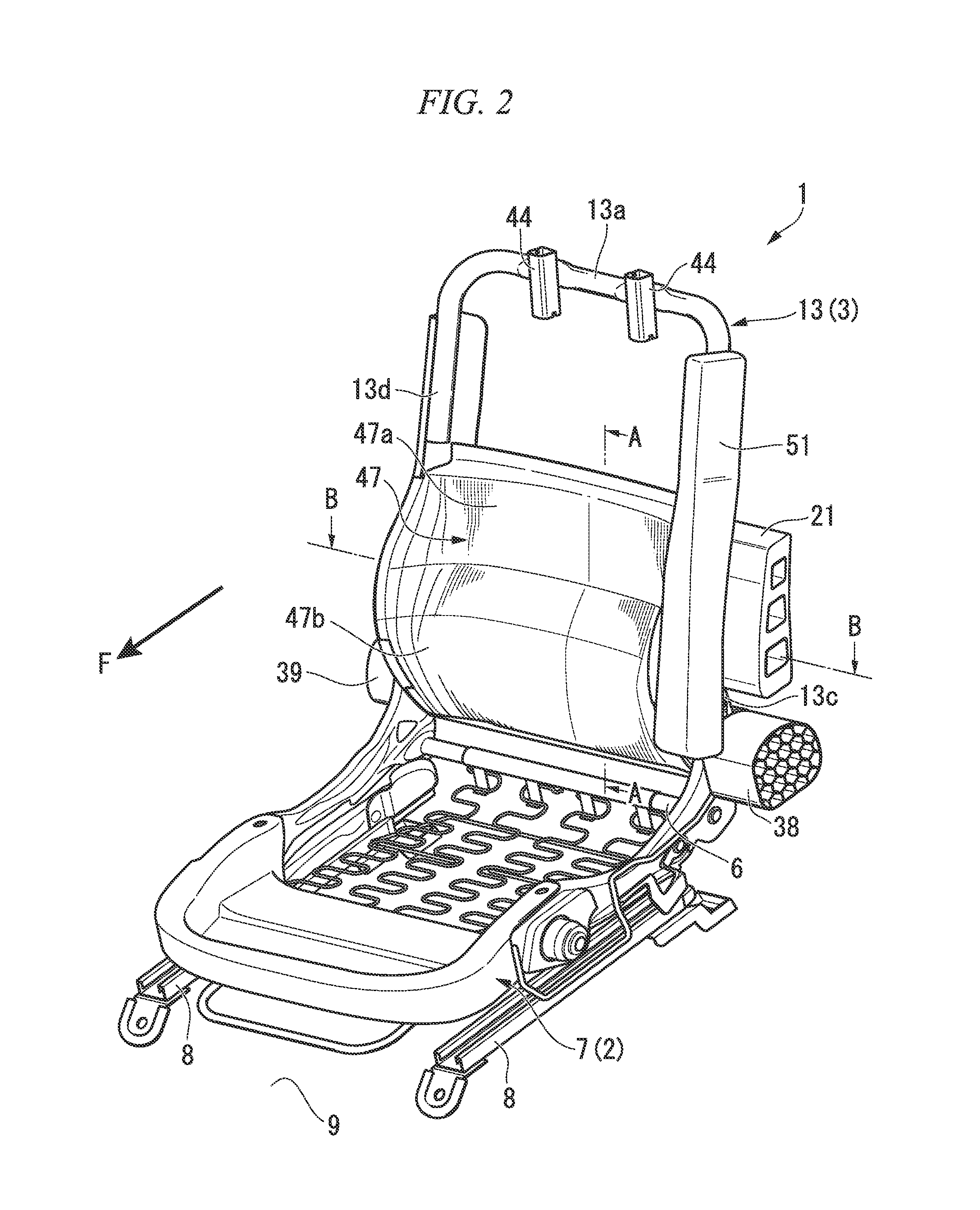
[0070]FIG. 1 is a perspective view seen obliquely upward from the front side of a vehicle seat 1 provided in a front seat side of a vehicle, and FIG. 2 is a perspective view seen obliquely upward from the front side of a skeleton of the vehicle seat 1.
[0071]The vehicle seat 1 includes a seat cushion 2 that supports the buttocks of an occupant, a seat back 3 that is connected to a rear end part of the seat cushion 2 and mainly supports the waist or the chest (rear side) of an occupant, and a headrest 4 that is supported by an upper part of the seat back 3 and supports the head and the neck of the occupant.
[0072]As shown in FIG. 2, the seat cushion 2 includes a cushion frame 7 in which a rear cross member 6 extended in the vehicle width direction is att...
second embodiment
(2) Second Embodiment
[0100]Hereinafter, a vehicle seat according to the second embodiment of the present invention will be described with reference to FIGS. 7 to 13. Further, in the drawings, an arrow F indicates the front side of the vehicle.
[0101]FIG. 7 is a perspective view seen obliquely upward from the front side of a vehicle seat 101 mounted in the front seat side of the vehicle, and FIG. 8 is a perspective view seen obliquely upward from the front side a skeleton of the vehicle seat 101 in the similar manner.
[0102]The vehicle seat 101 includes a seat cushion 102 that supports the hip of the occupant, a seat back 103 that is connected to the rear end of the seat cushion 102 and mainly supports the waist and the chest (the back part) of the occupant, and a headrest (not shown) that is supported by the upper part of the seat back 103 and supports the head and the neck of the occupant.
[0103]As shown in FIG. 8, the seat cushion 102 includes a cushion frame 107 in which a rear cros...
third embodiment
(3) Third Embodiment
[0131]Hereinafter, a vehicle seat according to a third embodiment of the present invention will be described with reference to FIGS. 14 to 22. Further, in the drawings, an arrow F indicates a front side of the vehicle.
[0132]FIG. 14 is a perspective view seen obliquely upward from the front side the vehicle seat 201 mounted in the front seat side of the vehicle, and FIG. 15 is a perspective view seen obliquely upward from the front side of a skeleton of the vehicle seat 201.
[0133]The vehicle seat 201 includes a seat cushion 202 that supports the hip of the occupant, a seat back 203 that is connected to the rear end part of the seat cushion 202, and mainly supports the waist and the chest (rear part) of the occupant, and a headrest (not shown) that is supported by an upper part of the seat back 203 and that supports the head and the neck of the occupant.
[0134]As shown in FIG. 15, the seat cushion 202 includes a cushion frame 207 in which a rear cross member 206 ext...
PUM
 Abstract
Description
Claims
Application Information